Panasonic WJ-HD716/1000 Installation Guide - Page 29
Connections
 |
View all Panasonic WJ-HD716/1000 manuals
Add to My Manuals
Save this manual to your list of manuals |
Page 29 highlights
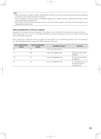
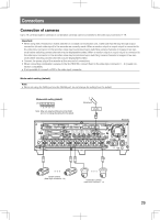
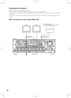
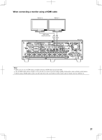
Connections Connection of cameras Up to 16 cameras (system cameras or combination cameras) can be connected to the video input connector 1-16. Important: • When using with a Panasonic's matrix switcher or a coaxial communication unit, make sure that the loop-through output connection (of each video input) to the recorder are correctly made. When a monitor output or a spot output is connected to the video input connector of the recorder, noise may be produced upon switching camera channels or images of few seconds before switching camera channels may be displayed/recorded. When a monitor output or a spot output is connected to the video input connector of the recorder, noise may be produced upon switching camera channels or images of few seconds before switching camera channels may be displayed/recorded. • Connect the power plug of the recorder at the very end of connections. • When connecting combination cameras to the WJ-HD616K, connect them to the video input connector 1 - 8 (coaxial connection compatible). • It is impossible to connect a VCR to the video input connector. Mode switch setting (default) Note: • When not using the DATA port and the RS485 port, do not change the setting from the default. Mode switch setting (default) ON 12345678 Note: When not using the DATA port and the RS485 port, do not change the setting from the default. Microphone Amplifier IN OUT EXT STORAGE MODE DATA RS485(CAMERA) 10/100BASE-T 3 2 ALARM ALARM/CONTROL 1 1 MONITOR OUT 2 OUT-CASCADE-IN 12345678 2 2 1 2 1 CASCADE IN OUT MONITOR OUT(HD) 1 3 1 IN CASCADE OUT 4 2 AUDIO AUDIO IN OUT 16 15 14 13 12 11 10 9 8 7 6 5 4 3 2 1 7 1 OUT 16 15 14 13 12 11 10 9 8 7 6 5 4 3 2 VIDEO Recorder POWER ON OFF AC IN SIGNAL GND • • • System cameras (Video input connector 9 - 16) • • • Combination cameras (Video input connector 1 - 8) 29
-
 1
1 -
2
-
3
-
4
-
5
-
6
-
7
-
8
-
9
-
10
-
11
-
12
-
13
-
14
-
15
-
16
-
17
-
18
-
19
-
20
-
21
-
22
-
23
-
 24
24 -
 25
25 -
 26
26 -
 27
27 -
 28
28 -
 29
29 -
 30
30 -
 31
31 -
 32
32 -
 33
33 -
 34
34 -
35
-
36
-
37
-
38
-
39
-
40
-
41
-
42
-
43
-
44
-
45
-
46
-
47
-
48
-
49
-
50
-
51
-
52
-
53
-
54
-
55
-
56
-
57
-
58
-
59
-
60
-
61
-
62
-
63
-
64
-
65
-
66
-
67
-
68
-
69
-
70
-
71
-
72
-
73
-
74
-
75
-
76
-
77
-
78
-
79
-
80
-
81
-
82
-
83
-
84
-
85
-
86
-
87
-
88
-
89
-
90
-
91
-
92
-
93
-
94
-
95
-
96
-
97
-
98
-
99
-
100
-
101
-
102
-
103
-
104
-
105
-
106
-
107
-
108
-
109
-
110
-
111
-
112
-
113
-
114
-
115
-
116
-
117
-
118
-
119
-
120
-
121
-
122
-
123
-
124
-
125
-
126
-
127
-
128
-
129
-
130
-
131
-
132
-
133
-
134
-
135
-
136
-
137
-
138
-
139
-
140
-
141
-
142
-
143
-
144
-
145
-
146
-
147
-
148
-
149
-
150
-
151
-
152
-
153
-
154
-
155
-
156
 |
 |
