ZyXEL NBG6515 User Guide - Page 15
The WPS Button, Wall Mounting - user manual
 |
View all ZyXEL NBG6515 manuals
Add to My Manuals
Save this manual to your list of manuals |
Page 15 highlights
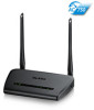
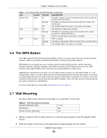
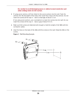
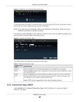
Chapter 1 Getting to Know Your NBG Table 1 Front Panel LEDs and WPS Button (continued) LED COLOR STATUS DESCRIPTION WLAN 5 GHz Green On The NBG is ready, but is not sending/receiving data through the wireless LAN 5 GHz band. Blinking The NBG is sending/receiving data through the wireless LAN 5 GHz band. Off The wireless LAN 5 GHz band is not ready or has failed. USB Green On The NBG has a USB device installed. Blinking The NBG is transmitting and/or receiving data from routers through an installed USB device. Off There is no USB device connected to the NBG. WPS Green On WPS is enabled. Blinking The NBG is negotiating a WPS connection with a wireless client. Off The wireless LAN is not ready or has failed. 1.6 The WPS Button Your NBG supports WiFi Protected Setup (WPS), which is an easy way to set up a secure wireless network. WPS is an industry standard specification, defined by the WiFi Alliance. WPS allows you to quickly set up a wireless network with strong security, without having to configure security settings manually. Each WPS connection works between two devices. Both devices must support WPS (check each device's documentation to make sure). Depending on the devices you have, you can either press a button (on the device itself, or in its configuration utility) or enter a PIN (a unique Personal Identification Number that allows one device to authenticate the other) in each of the two devices. When WPS is activated on a device, it has two minutes to find another device that also has WPS activated. Then, the two devices connect and set up a secure network by themselves. For more information on using WPS, see Section 10.3 on page 72. 1.7 Wall Mounting You may need screw anchors if mounting on a concrete or brick wall. Table 2 Wall Mounting Information Distance between holes M4 Screws Screw anchors (optional) 11 cm Two Two 1 Select a position free of obstructions on a wall strong enough to hold the weight of the device. 2 Mark two holes on the wall at the appropriate distance apart for the screws. NBG6515 User's Guide 15
-
 1
1 -
2
-
3
-
4
-
5
-
6
-
7
-
8
-
9
-
 10
10 -
 11
11 -
 12
12 -
 13
13 -
 14
14 -
 15
15 -
 16
16 -
 17
17 -
 18
18 -
 19
19 -
 20
20 -
21
-
22
-
23
-
24
-
25
-
26
-
27
-
28
-
29
-
30
-
31
-
32
-
33
-
34
-
35
-
36
-
37
-
38
-
39
-
40
-
41
-
42
-
43
-
44
-
45
-
46
-
47
-
48
-
49
-
50
-
51
-
52
-
53
-
54
-
55
-
56
-
57
-
58
-
59
-
60
-
61
-
62
-
63
-
64
-
65
-
66
-
67
-
68
-
69
-
70
-
71
-
72
-
73
-
74
-
75
-
76
-
77
-
78
-
79
-
80
-
81
-
82
-
83
-
84
-
85
-
86
-
87
-
88
-
89
-
90
-
91
-
92
-
93
-
94
-
95
-
96
-
97
-
98
-
99
-
100
-
101
-
102
-
103
-
104
-
105
-
106
-
107
-
108
-
109
-
110
-
111
-
112
-
113
-
114
-
115
-
116
-
117
-
118
-
119
-
120
-
121
-
122
-
123
-
124
-
125
-
126
-
127
-
128
-
129
-
130
-
131
-
132
-
133
-
134
-
135
-
136
-
137
-
138
-
139
-
140
-
141
-
142
-
143
-
144
-
145
-
146
-
147
-
148
-
149
-
150
-
151
-
152
-
153
-
154
-
155
-
156
-
157
-
158
-
159
-
160
-
161
-
162
-
163
-
164
-
165
-
166
-
167
-
168
-
169
-
170
-
171
-
172
-
173
-
174
-
175
-
176
-
177
-
178
-
179
-
180
-
181
-
182
-
183
-
184
-
185
-
186
-
187
-
188
-
189
-
190
-
191
-
192
-
193
-
194
-
195
-
196
-
197
-
198
-
199
-
200
-
201
-
202
-
203
-
204
-
205
-
206
-
207
-
208
-
209
-
210
-
211
-
212
-
213
-
214
-
215
-
216
-
217
-
218
-
219
-
220
-
221
-
222
-
223
-
224
-
225
-
226
-
227
-
228
-
229
-
230
-
231
-
232
-
233
-
234
-
235
-
236
-
237
-
238
-
239
-
240
-
241
-
242
-
243
-
244
-
245
-
246
-
247
-
248
-
249
 |
 |
