Dell XPS M2010 Owner's Manual - Page 130
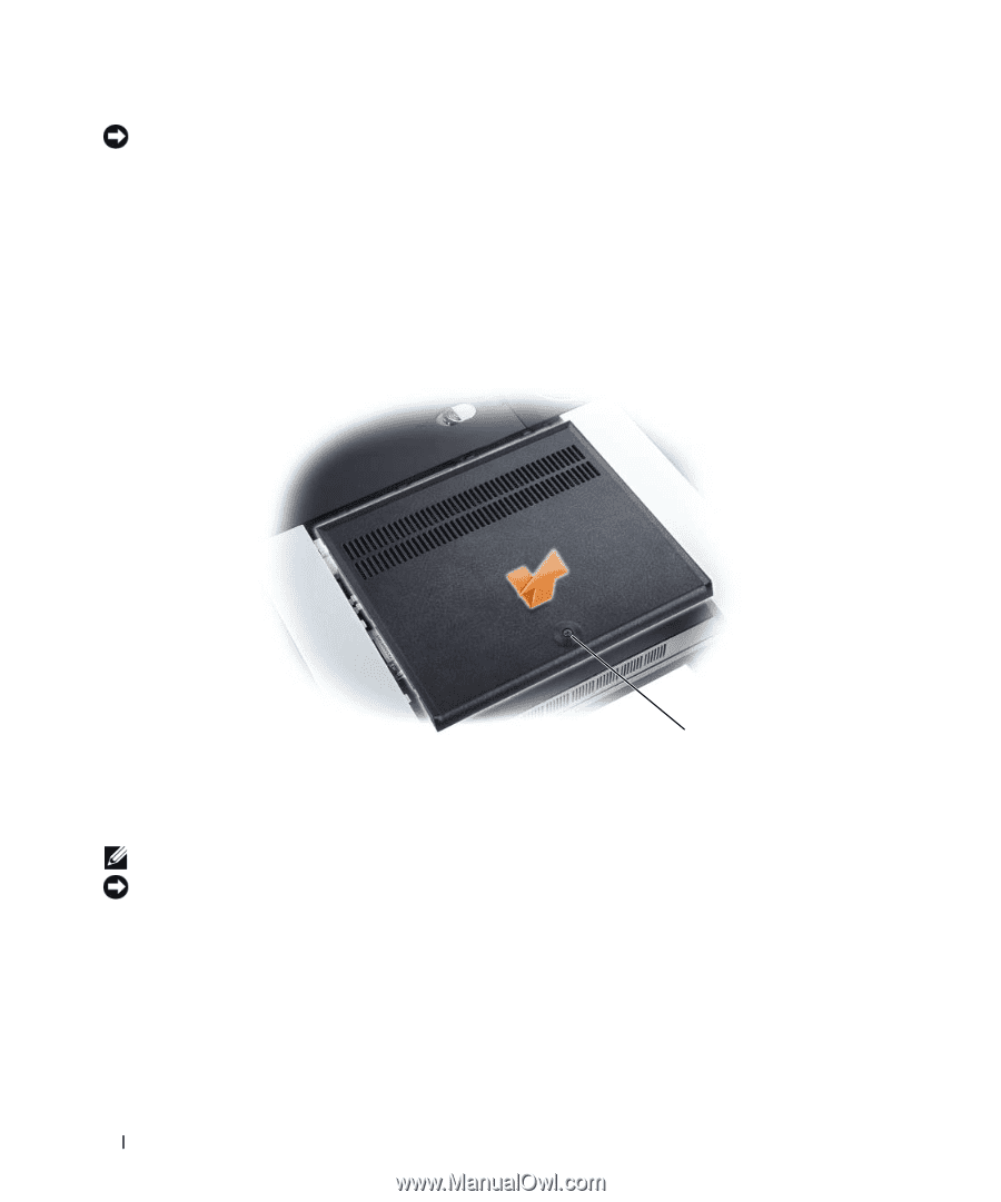
The computer has two memory slots, DIMM A and DIMM B, located under the memory module cover.
 |
View all Dell XPS M2010 manuals
Add to My Manuals
Save this manual to your list of manuals |
Page 130 highlights
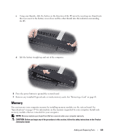
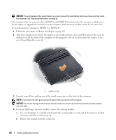
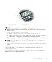
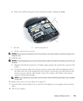
NOTICE: To avoid damaging the system board, you must remove the main battery before you begin working inside the computer. See "Replacing the Battery" on page 55. The computer has two memory slots, DIMM A and DIMM B, located under the memory module cover. If you replace or upgrade the memory in your computer, both memory modules must be the same size. To install a memory module in DIMM A or DIMM B: 1 Follow the procedures in "Before You Begin" on page 127. 2 Turn the computer over, loosen the captive screw on the memory cover, and then remove the cover by sliding it toward the back of the computer to disengage the tabs on the base from the notches in the cover, then lifting the cover off. 1 1 captive screw 3 Ground yourself by touching one of the metal connectors on the back of the computer. NOTE: If you leave the area, ground yourself again when you return to the computer. NOTICE: To prevent damage to the memory module connector, do not use tools to spread the memory-module securing clips. 4 If you are replacing a memory module, remove the existing module: a Use your fingertips to carefully spread apart the securing clips on each end of the memory module connector until the module pops up. b Remove the module from the connector. 130 Adding and Replacing Parts
-
 1
1 -
2
-
3
-
4
-
5
-
6
-
7
-
8
-
9
-
10
-
11
-
12
-
13
-
14
-
15
-
16
-
17
-
18
-
19
-
20
-
21
-
22
-
23
-
24
-
25
-
26
-
27
-
28
-
29
-
30
-
31
-
32
-
33
-
34
-
35
-
36
-
37
-
38
-
39
-
40
-
41
-
42
-
43
-
44
-
45
-
46
-
47
-
48
-
49
-
50
-
51
-
52
-
53
-
54
-
55
-
56
-
57
-
58
-
59
-
60
-
61
-
62
-
63
-
64
-
65
-
66
-
67
-
68
-
69
-
70
-
71
-
72
-
73
-
74
-
75
-
76
-
77
-
78
-
79
-
80
-
81
-
82
-
83
-
84
-
85
-
86
-
87
-
88
-
89
-
90
-
91
-
92
-
93
-
94
-
95
-
96
-
97
-
98
-
99
-
100
-
101
-
102
-
103
-
104
-
105
-
106
-
107
-
108
-
109
-
110
-
111
-
112
-
113
-
114
-
115
-
116
-
117
-
118
-
119
-
120
-
121
-
122
-
123
-
124
-
 125
125 -
 126
126 -
 127
127 -
 128
128 -
 129
129 -
 130
130 -
 131
131 -
 132
132 -
 133
133 -
 134
134 -
 135
135 -
136
-
137
-
138
-
139
-
140
-
141
-
142
-
143
-
144
-
145
-
146
-
147
-
148
-
149
-
150
-
151
-
152
-
153
-
154
-
155
-
156
-
157
-
158
-
159
-
160
-
161
-
162
-
163
-
164
-
165
-
166
-
167
-
168
-
169
-
170
-
171
-
172
-
173
-
174
-
175
-
176
-
177
-
178
-
179
-
180
-
181
-
182
-
183
-
184
-
185
-
186
-
187
-
188
-
189
-
190
-
191
-
192
-
193
-
194
 |
 |