HP 6125G HP 6125G & 6125G/XG Blade Switches Network Management and Mon - Page 147
Configuring counter sampling, Displaying and maintaining sFlow, sFlow configuration example, Network
 |
View all HP 6125G manuals
Add to My Manuals
Save this manual to your list of manuals |
Page 147 highlights
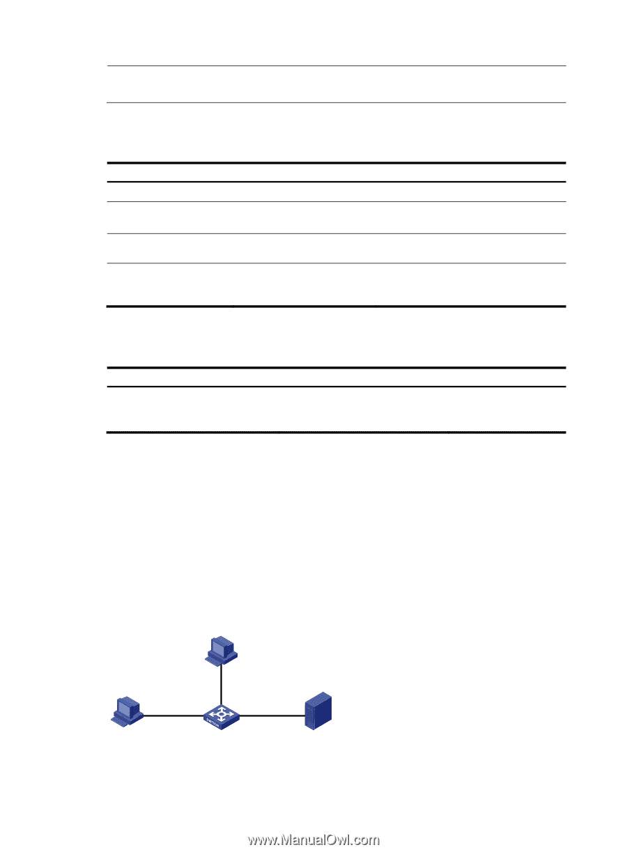
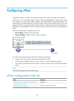
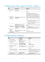
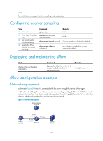
NOTE: The switch does not support the flow sampling mode determine. Configuring counter sampling Step 1. Enter system view. 2. Enter Layer 2 interface view. 3. Set the interval for counter sampling. 4. Specify the sFlow collector for counter sampling. Command system-view interface interface-type interface-number sflow counter interval seconds sflow counter collector collector-id Remarks N/A N/A Counter sampling is disabled by default. No collector is specified for counter sampling by default. Displaying and maintaining sFlow Task Display sFlow configuration information. Command display sflow [ slot slot-number ] [ | { begin | exclude | include } regular-expression ] Remarks Available in any view sFlow configuration example Network requirements As shown in Figure 51, Host A is connected with the server through the device (sFlow agent). Enable sFlow (including flow sampling and counter sampling) on GigabitEthernet 1/0/1 to monitor traffic on the interface. The device sends sFlow packets through GigabitEthernet 1/0/3 to the sFlow collector, which analyzes the sFlow packets and displays results. Figure 51 Network diagram sFlow Collector 3.3.3.2/16 Host A 1.1.1.1/16 VLAN 1 3.3.3.1/16 GE1/0/1 1.1.1.2/16 Device GE1/0/2 2.2.2.1/16 Server 2.2.2.2/16 140
-
 1
1 -
2
-
3
-
4
-
5
-
6
-
7
-
8
-
9
-
10
-
11
-
12
-
13
-
14
-
15
-
16
-
17
-
18
-
19
-
20
-
21
-
22
-
23
-
24
-
25
-
26
-
27
-
28
-
29
-
30
-
31
-
32
-
33
-
34
-
35
-
36
-
37
-
38
-
39
-
40
-
41
-
42
-
43
-
44
-
45
-
46
-
47
-
48
-
49
-
50
-
51
-
52
-
53
-
54
-
55
-
56
-
57
-
58
-
59
-
60
-
61
-
62
-
63
-
64
-
65
-
66
-
67
-
68
-
69
-
70
-
71
-
72
-
73
-
74
-
75
-
76
-
77
-
78
-
79
-
80
-
81
-
82
-
83
-
84
-
85
-
86
-
87
-
88
-
89
-
90
-
91
-
92
-
93
-
94
-
95
-
96
-
97
-
98
-
99
-
100
-
101
-
102
-
103
-
104
-
105
-
106
-
107
-
108
-
109
-
110
-
111
-
112
-
113
-
114
-
115
-
116
-
117
-
118
-
119
-
120
-
121
-
122
-
123
-
124
-
125
-
126
-
127
-
128
-
129
-
130
-
131
-
132
-
133
-
134
-
135
-
136
-
137
-
138
-
139
-
140
-
141
-
 142
142 -
 143
143 -
 144
144 -
 145
145 -
 146
146 -
 147
147 -
 148
148 -
 149
149 -
 150
150 -
 151
151 -
 152
152 -
153
-
154
-
155
-
156
-
157
 |
 |