HP 6125G HP 6125G & 6125G/XG Blade Switches Network Management and Mon - Page 92
Assigning the monitor port to the remote probe VLAN, Displaying and maintaining port mirroring
 |
View all HP 6125G manuals
Add to My Manuals
Save this manual to your list of manuals |
Page 92 highlights
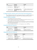
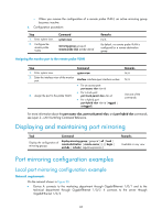
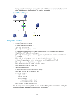
{ When you remove the configuration of a remote probe VLAN, an active mirroring group becomes inactive. 2. Configuration procedure: Step 1. Enter system view. 2. Configure the remote probe VLAN. Command system-view mirroring-group group-id remote-probe vlan rprobe-vlan-id Remarks N/A By default, no remote probe VLAN is configured for a remote destination group. Assigning the monitor port to the remote probe VLAN Step 1. Enter system view. 2. Enter the interface view of the monitor port. 3. Assign the port to the probe VLAN. Command system-view interface interface-type interface-number • For an access port: port access vlan vlan-id • For a trunk port: port trunk permit vlan vlan-id • For a hybrid port: port hybrid vlan vlan-id { tagged | untagged } Remarks N/A N/A Use one of the commands. For more information about the port access vlan, port trunk permit vlan, and port hybrid vlan commands, see Layer 2-LAN Switching Command Reference. Displaying and maintaining port mirroring Task Command Display the configuration of mirroring groups. display mirroring-group { group-id | all | local | remote-destination | remote-source } [ | { begin | exclude | include } regular-expression ] Remarks Available in any view Port mirroring configuration examples Local port mirroring configuration example Network requirements On the network shown in Figure 33: • Device A connects to the marketing department through GigabitEthernet 1/0/1 and to the technical department through GigabitEthernet 1/0/2. It connects to the server through GigabitEthernet 1/0/3. 85
-
 1
1 -
2
-
3
-
4
-
5
-
6
-
7
-
8
-
9
-
10
-
11
-
12
-
13
-
14
-
15
-
16
-
17
-
18
-
19
-
20
-
21
-
22
-
23
-
24
-
25
-
26
-
27
-
28
-
29
-
30
-
31
-
32
-
33
-
34
-
35
-
36
-
37
-
38
-
39
-
40
-
41
-
42
-
43
-
44
-
45
-
46
-
47
-
48
-
49
-
50
-
51
-
52
-
53
-
54
-
55
-
56
-
57
-
58
-
59
-
60
-
61
-
62
-
63
-
64
-
65
-
66
-
67
-
68
-
69
-
70
-
71
-
72
-
73
-
74
-
75
-
76
-
77
-
78
-
79
-
80
-
81
-
82
-
83
-
84
-
85
-
86
-
 87
87 -
 88
88 -
 89
89 -
 90
90 -
 91
91 -
 92
92 -
 93
93 -
 94
94 -
 95
95 -
 96
96 -
 97
97 -
98
-
99
-
100
-
101
-
102
-
103
-
104
-
105
-
106
-
107
-
108
-
109
-
110
-
111
-
112
-
113
-
114
-
115
-
116
-
117
-
118
-
119
-
120
-
121
-
122
-
123
-
124
-
125
-
126
-
127
-
128
-
129
-
130
-
131
-
132
-
133
-
134
-
135
-
136
-
137
-
138
-
139
-
140
-
141
-
142
-
143
-
144
-
145
-
146
-
147
-
148
-
149
-
150
-
151
-
152
-
153
-
154
-
155
-
156
-
157
 |
 |