HP 6125G HP 6125G & 6125G/XG Blade Switches Network Management and Mon - Page 94
Layer 2 remote port mirroring configuration example, Network requirements, Configuration procedure
 |
View all HP 6125G manuals
Add to My Manuals
Save this manual to your list of manuals |
Page 94 highlights
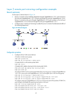
Layer 2 remote port mirroring configuration example Network requirements On the Layer 2 network shown in Figure 34: • Device A connects to the marketing department through GigabitEthernet 1/0/1 and connects to the trunk port GigabitEthernet 1/0/1 of Device B through the trunk port GigabitEthernet 1/0/2. Device C connects to the server through GigabitEthernet 1/0/2 and connects to the trunk port GigabitEthernet 1/0/2 of Device B through the trunk port GigabitEthernet 1/0/1. • Configure Layer 2 remote port mirroring to enable the server to monitor the bidirectional traffic of the marketing department. Figure 34 Network diagram Configuration procedure 1. Configure Device A (the source device): # Create a remote source group. system-view [DeviceA] mirroring-group 1 remote-source # Create VLAN 2 as the remote probe VLAN. [DeviceA] vlan 2 # Disable MAC address learning for the remote probe VLAN. [DeviceA-vlan2] mac-address mac-learning disable [DeviceA-vlan2] quit # Configure VLAN 2 as the remote probe VLAN of the mirroring group. Configure GigabitEthernet 1/0/1 as a source port and GigabitEthernet 1/0/2 as the egress port in the mirroring group. [DeviceA] mirroring-group 1 remote-probe vlan 2 [DeviceA] mirroring-group 1 mirroring-port GigabitEthernet 1/0/1 both [DeviceA] mirroring-group 1 monitor-egress GigabitEthernet 1/0/2 # Configure output port GigabitEthernet 1/0/2 as a trunk port to permit the packets of VLAN 2 to pass through, and disable the spanning tree feature on the port. [DeviceA] interface GigabitEthernet 1/0/2 [DeviceA-GigabitEthernet1/0/2] port link-type trunk [DeviceA-GigabitEthernet1/0/2] port trunk permit vlan 2 [DeviceA-GigabitEthernet1/0/2] undo stp enable 87
-
 1
1 -
2
-
3
-
4
-
5
-
6
-
7
-
8
-
9
-
10
-
11
-
12
-
13
-
14
-
15
-
16
-
17
-
18
-
19
-
20
-
21
-
22
-
23
-
24
-
25
-
26
-
27
-
28
-
29
-
30
-
31
-
32
-
33
-
34
-
35
-
36
-
37
-
38
-
39
-
40
-
41
-
42
-
43
-
44
-
45
-
46
-
47
-
48
-
49
-
50
-
51
-
52
-
53
-
54
-
55
-
56
-
57
-
58
-
59
-
60
-
61
-
62
-
63
-
64
-
65
-
66
-
67
-
68
-
69
-
70
-
71
-
72
-
73
-
74
-
75
-
76
-
77
-
78
-
79
-
80
-
81
-
82
-
83
-
84
-
85
-
86
-
87
-
88
-
 89
89 -
 90
90 -
 91
91 -
 92
92 -
 93
93 -
 94
94 -
 95
95 -
 96
96 -
 97
97 -
 98
98 -
 99
99 -
100
-
101
-
102
-
103
-
104
-
105
-
106
-
107
-
108
-
109
-
110
-
111
-
112
-
113
-
114
-
115
-
116
-
117
-
118
-
119
-
120
-
121
-
122
-
123
-
124
-
125
-
126
-
127
-
128
-
129
-
130
-
131
-
132
-
133
-
134
-
135
-
136
-
137
-
138
-
139
-
140
-
141
-
142
-
143
-
144
-
145
-
146
-
147
-
148
-
149
-
150
-
151
-
152
-
153
-
154
-
155
-
156
-
157
 |
 |
