HP 6125G HP 6125G & 6125G/XG Blade Switches Network Management and Mon - Page 20
Symmetric peers mode, Broadcast mode,
 |
View all HP 6125G manuals
Add to My Manuals
Save this manual to your list of manuals |
Page 20 highlights
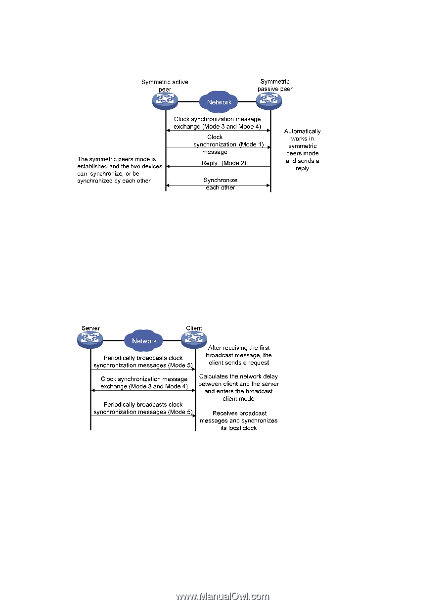
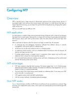
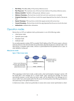
Symmetric peers mode Figure 8 Symmetric peers mode In symmetric peers mode, devices that operate in symmetric active mode and symmetric passive mode exchange NTP messages with the Mode field 3 (client mode) and 4 (server mode). Then the device that operates in symmetric active mode periodically sends clock synchronization messages, with the Mode field in the messages set to 1 (symmetric active). The device that receives the messages automatically enters symmetric passive mode and sends a reply, with the Mode field in the message set to 2 (symmetric passive). This exchange of messages establishes symmetric peers mode between the two devices, so the two devices can synchronize, or be synchronized by, each other. If the clocks of both devices have been synchronized, the device whose local clock has a lower stratum level synchronizes the other device. Broadcast mode Figure 9 Broadcast mode In broadcast mode, a server periodically sends clock synchronization messages to broadcast address 255.255.255.255, with the Mode field in the messages set to 5 (broadcast mode). Clients listen to the broadcast messages from servers. When a client receives the first broadcast message, the client and the server start to exchange messages with the Mode field set to 3 (client mode) and 4 (server mode), to calculate the network delay between client and the server. Then, the client enters broadcast client mode. The client continues listening to broadcast messages, and synchronizes its local clock based on the received broadcast messages. 13
-
 1
1 -
2
-
3
-
4
-
5
-
6
-
7
-
8
-
9
-
10
-
11
-
12
-
13
-
14
-
 15
15 -
 16
16 -
 17
17 -
 18
18 -
 19
19 -
 20
20 -
 21
21 -
 22
22 -
 23
23 -
 24
24 -
 25
25 -
26
-
27
-
28
-
29
-
30
-
31
-
32
-
33
-
34
-
35
-
36
-
37
-
38
-
39
-
40
-
41
-
42
-
43
-
44
-
45
-
46
-
47
-
48
-
49
-
50
-
51
-
52
-
53
-
54
-
55
-
56
-
57
-
58
-
59
-
60
-
61
-
62
-
63
-
64
-
65
-
66
-
67
-
68
-
69
-
70
-
71
-
72
-
73
-
74
-
75
-
76
-
77
-
78
-
79
-
80
-
81
-
82
-
83
-
84
-
85
-
86
-
87
-
88
-
89
-
90
-
91
-
92
-
93
-
94
-
95
-
96
-
97
-
98
-
99
-
100
-
101
-
102
-
103
-
104
-
105
-
106
-
107
-
108
-
109
-
110
-
111
-
112
-
113
-
114
-
115
-
116
-
117
-
118
-
119
-
120
-
121
-
122
-
123
-
124
-
125
-
126
-
127
-
128
-
129
-
130
-
131
-
132
-
133
-
134
-
135
-
136
-
137
-
138
-
139
-
140
-
141
-
142
-
143
-
144
-
145
-
146
-
147
-
148
-
149
-
150
-
151
-
152
-
153
-
154
-
155
-
156
-
157
 |
 |