HP DL360 HP ProLiant DL360 Generation 3 Server Setup and Installation Guide - Page 112
Class B regulations, Federal Communications Commission
 |
UPC - 613326948835
View all HP DL360 manuals
Add to My Manuals
Save this manual to your list of manuals |
Page 112 highlights
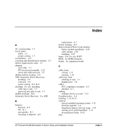
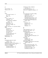
Index CDs HP Management 4-6 SmartStart 4-4 Class 1 laser product A-5 Class A regulations A-4 Class B regulations A-4 clearance, rack airflow 1-3 closing the cable straps 3-11 CMOS, clearing E-9 components, system board 2-6 configuration, server 4-1 configure-to-order system See factory-installed operating system connecting peripheral devices 3-8 power cord 3-8 connection, rear panel sequence 3-9 connectors rear panel, connection order 3-9 rear panel, illustrated 3-9 cord See power cord current load requirements 1-4 rated input F-1 rating A-8 D debug LED switch (SW3), settings E-8 declaration of conformity A-3 deployment white paper 1-1 devices, powerup sequence D-3 diagnosing problems See troubleshooting Diagnostics Utility 4-7 DIMMs installation, guidelines 2-7 installation, procedure 2-8 disaster recovery 4-2 disengaging the rail-release latches 2-5 diskette drive, troubleshooting D-10 disposal, battery A-8 dissipating floor mats B-2 documentation, required for installation 1-7 drivers, additional information D-9 E electric shock, warning D-6, D-7 electrostatic discharge overview B-1 prevention measures B-1 environmental requirements 1-3 equipment Class A A-2 Class B A-2 error checking and correcting (ECC), DIMM restrictions 2-7 error messages, additional information C-1 European Union Notice A-4 event notification, Insight Manager D-2, D-9 expansion boards installation 2-11 procedures 2-9 expansion slot cover 2-11 F factory-installed operating system troubleshooting D-12 fastening cable tray to the server 3-6 FCC See Federal Communications Commission (FCC) features, software 4-1 Federal Communications Commission (FCC) compliance notice, Class A A-2 compliance notice, Class B A-2 declaration of conformity A-3 notice A-1 requirements A-3 rules A-2, A-3 firmware, upgrading 4-3 fixed rail locking bracket 3-7 flash ROM 4-3 frequency, rated input F-1 Index-2 HP ProLiant DL360 Generation 3 Server Setup and Installation Guide
-
 1
1 -
2
-
3
-
4
-
5
-
6
-
7
-
8
-
9
-
10
-
11
-
12
-
13
-
14
-
15
-
16
-
17
-
18
-
19
-
20
-
21
-
22
-
23
-
24
-
25
-
26
-
27
-
28
-
29
-
30
-
31
-
32
-
33
-
34
-
35
-
36
-
37
-
38
-
39
-
40
-
41
-
42
-
43
-
44
-
45
-
46
-
47
-
48
-
49
-
50
-
51
-
52
-
53
-
54
-
55
-
56
-
57
-
58
-
59
-
60
-
61
-
62
-
63
-
64
-
65
-
66
-
67
-
68
-
69
-
70
-
71
-
72
-
73
-
74
-
75
-
76
-
77
-
78
-
79
-
80
-
81
-
82
-
83
-
84
-
85
-
86
-
87
-
88
-
89
-
90
-
91
-
92
-
93
-
94
-
95
-
96
-
97
-
98
-
99
-
100
-
101
-
102
-
103
-
104
-
105
-
106
-
 107
107 -
 108
108 -
 109
109 -
 110
110 -
 111
111 -
 112
112 -
 113
113 -
 114
114 -
 115
115 -
 116
116 -
 117
117 -
118
 |
 |