HP DL360 HP ProLiant DL360 Generation 3 Server Setup and Installation Guide - Page 45
Reinstall the PCI riser board assembly into slot 1.
 |
UPC - 613326948835
View all HP DL360 manuals
Add to My Manuals
Save this manual to your list of manuals |
Page 45 highlights
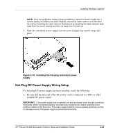
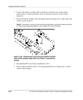
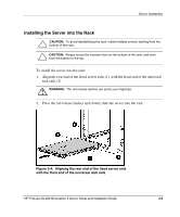
Installing Hardware Options 3. Connect the battery module cable to the battery-backed write cache enabler battery pack (1) and to the Smart Array 5i memory connector on the system board (2). 4. Route the battery module cable through the battery-backed write cache cable clip on the system board (3). NOTE: If necessary, remove the PCI riser board assembly to access the cable clip. Refer to "Removing an Expansion Board" in this chapter, for more information. Figure 2-22: Routing and connecting the battery-backed write cache enabler cable (PCI riser board 1 removed for clarity) 5. Reinstall the PCI riser board assembly into slot 1. 6. Reverse the procedures in the "Accessing Internal Server Components" section earlier in this chapter. 2-26 HP ProLiant DL360 Generation 3 Server Setup and Installation Guide
-
 1
1 -
2
-
3
-
4
-
5
-
6
-
7
-
8
-
9
-
10
-
11
-
12
-
13
-
14
-
15
-
16
-
17
-
18
-
19
-
20
-
21
-
22
-
23
-
24
-
25
-
26
-
27
-
28
-
29
-
30
-
31
-
32
-
33
-
34
-
35
-
36
-
37
-
38
-
39
-
 40
40 -
 41
41 -
 42
42 -
 43
43 -
 44
44 -
 45
45 -
 46
46 -
 47
47 -
 48
48 -
 49
49 -
 50
50 -
51
-
52
-
53
-
54
-
55
-
56
-
57
-
58
-
59
-
60
-
61
-
62
-
63
-
64
-
65
-
66
-
67
-
68
-
69
-
70
-
71
-
72
-
73
-
74
-
75
-
76
-
77
-
78
-
79
-
80
-
81
-
82
-
83
-
84
-
85
-
86
-
87
-
88
-
89
-
90
-
91
-
92
-
93
-
94
-
95
-
96
-
97
-
98
-
99
-
100
-
101
-
102
-
103
-
104
-
105
-
106
-
107
-
108
-
109
-
110
-
111
-
112
-
113
-
114
-
115
-
116
-
117
-
118
 |
 |
