HP DL360 HP ProLiant DL360 Generation 3 Server Setup and Installation Guide - Page 98
Front Panel LED Indicators, E-1, Identifying the front panel LED indicators, Table E-1
 |
UPC - 613326948835
View all HP DL360 manuals
Add to My Manuals
Save this manual to your list of manuals |
Page 98 highlights
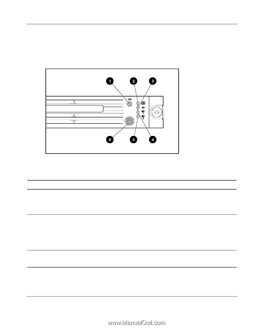
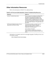
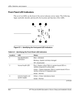
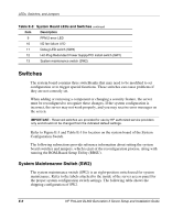
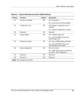
LEDs, Switches, and Jumpers Front Panel LED Indicators The set of six LEDs on the front of the server indicates server status. The following figure and table identify and describe the location and function of the LEDs. Figure E-1: Identifying the front panel LED indicators Table E-1: Identifying the Front Panel LED Indicators Location 1 LED Unit Identification LED/button 2 Internal health LED 3 External health LED (power supply) Status Blue = Activated Blinking = System remotely managed Off = Deactivated Red = System critical. Refer to system board LEDs to identify component in critical state. Amber = System degraded. Refer to system board LEDs to identify component in degraded state. Green = Normal Amber = Power redundancy failure Green = Normal continued E-2 HP ProLiant DL360 Generation 3 Server Setup and Installation Guide
-
 1
1 -
2
-
3
-
4
-
5
-
6
-
7
-
8
-
9
-
10
-
11
-
12
-
13
-
14
-
15
-
16
-
17
-
18
-
19
-
20
-
21
-
22
-
23
-
24
-
25
-
26
-
27
-
28
-
29
-
30
-
31
-
32
-
33
-
34
-
35
-
36
-
37
-
38
-
39
-
40
-
41
-
42
-
43
-
44
-
45
-
46
-
47
-
48
-
49
-
50
-
51
-
52
-
53
-
54
-
55
-
56
-
57
-
58
-
59
-
60
-
61
-
62
-
63
-
64
-
65
-
66
-
67
-
68
-
69
-
70
-
71
-
72
-
73
-
74
-
75
-
76
-
77
-
78
-
79
-
80
-
81
-
82
-
83
-
84
-
85
-
86
-
87
-
88
-
89
-
90
-
91
-
92
-
 93
93 -
 94
94 -
 95
95 -
 96
96 -
 97
97 -
 98
98 -
 99
99 -
 100
100 -
 101
101 -
 102
102 -
 103
103 -
104
-
105
-
106
-
107
-
108
-
109
-
110
-
111
-
112
-
113
-
114
-
115
-
116
-
117
-
118
 |
 |