HP DL360 HP ProLiant DL360 Generation 3 Server Setup and Installation Guide - Page 89
Table D-2, Front Panel Power-On/Standby LED Is Not On, The Next Step
 |
UPC - 613326948835
View all HP DL360 manuals
Add to My Manuals
Save this manual to your list of manuals |
Page 89 highlights
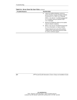
Troubleshooting Table D-2: Front Panel Power-On/Standby LED Is Not On WARNING: To reduce the risk of electric shock or damage to the equipment, before opening access panels to reseat components, power down the server, and then disconnect the power cord. Note: For LED locations and functions, refer to Appendix E, "LEDs, Switches, and Jumpers." Possible Reasons There is no AC power connection. The power button was not firmly pressed. The power button connector cable is not properly connected to the system board. A processor has failed or is not properly seated. The power supply has failed or is not connected. The Next Step 1. Be sure the power cables are fully connected. 2. Press the power button. 3. Confirm the power source is functioning. Refer to the Servers Troubleshooting Guide for further options. 4. Reconnect the power button cable to the system board. Refer to Chapter 2, "Installing Hardware Options," for the location of the power button connector. 5. Power down the server. Reseat all expansion boards, DIMMs, processors, and PPMs, confirming that all cables are securely connected. Refer to Chapter 2, "Installing Hardware Options," for complete instructions. Refer to the Servers Troubleshooting Guide for tips on proper procedures. 6. Monitor the diagnostic LEDs on the system board for failure conditions. If these steps do not correct the problem, the most likely cause lies either in the power supply subsystem or a processor. Contact an HP authorized service provider for further technical support. Refer to the Servers Troubleshooting Guide for a list of HP authorized service providers. D-6 HP ProLiant DL360 Generation 3 Server Setup and Installation Guide HP CONFIDENTIAL Writer: Richard O. Heath File Name: i-appd Troubleshooting.doc Codename: Ertl Part Number: 293974-001 Last Saved On: 10/11/02 11:23 AM
-
 1
1 -
2
-
3
-
4
-
5
-
6
-
7
-
8
-
9
-
10
-
11
-
12
-
13
-
14
-
15
-
16
-
17
-
18
-
19
-
20
-
21
-
22
-
23
-
24
-
25
-
26
-
27
-
28
-
29
-
30
-
31
-
32
-
33
-
34
-
35
-
36
-
37
-
38
-
39
-
40
-
41
-
42
-
43
-
44
-
45
-
46
-
47
-
48
-
49
-
50
-
51
-
52
-
53
-
54
-
55
-
56
-
57
-
58
-
59
-
60
-
61
-
62
-
63
-
64
-
65
-
66
-
67
-
68
-
69
-
70
-
71
-
72
-
73
-
74
-
75
-
76
-
77
-
78
-
79
-
80
-
81
-
82
-
83
-
 84
84 -
 85
85 -
 86
86 -
 87
87 -
 88
88 -
 89
89 -
 90
90 -
 91
91 -
 92
92 -
 93
93 -
 94
94 -
95
-
96
-
97
-
98
-
99
-
100
-
101
-
102
-
103
-
104
-
105
-
106
-
107
-
108
-
109
-
110
-
111
-
112
-
113
-
114
-
115
-
116
-
117
-
118
 |
 |