HP Dc7100 HP Compaq Business Desktop dc7100 Series Service Reference Guide, 3r - Page 107
Diskette Drive, enable the Smart Cover Sensor
 |
UPC - 829160356877
View all HP Dc7100 manuals
Add to My Manuals
Save this manual to your list of manuals |
Page 107 highlights
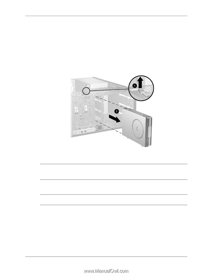
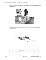
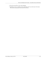
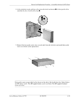
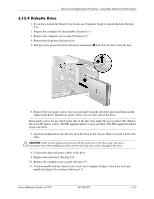
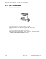
Removal and Replacement Procedures - Convertible Minitower (CMT) Chassis 6.13.4 Diskette Drive 1. If you have locked the Smart Cover Lock, use Computer Setup to unlock the lock (Section 6.2). 2. Prepare the computer for disassembly (Section 6.1). 3. Remove the computer access panel (Section 6.5). 4. Remove the front bezel (Section 6.6). 5. Pull up on the green hard drive drivelock mechanism 1 and slide the drive from the bay. 6. Remove the four guide screws (two on each side) from the old drive and install them in the replacement drive. Install four guide screws, two on each side of the drive. ✎ Extra guide screws are provided on the side of the drive bay under the access panel. The diskette drive use M3 metric screws. The HP-supplied metric screws are black. The HP-supplied standard screws are silver. 7. Insert the diskette drive into the bay from the front of the chassis. Push it in until it locks into place. Ä CAUTION: Make sure the guide screws line up with the guide slots in the drive cage. The use of unnecesary force when installing any drive into the drive bay may result in damage to the drive. 8. Connect the data and power cables to the drive. 9. Replace the front bezel (Section 6.6). 10. Replace the computer access panel (Section 6.5) 11. If you normally lock the Smart Cover Lock, use Computer Setup to relock the lock and enable the Smart Cover Sensor (Section 6.2). Service Reference Guide, dc7100 361288-003 6-27
-
 1
1 -
2
-
3
-
4
-
5
-
6
-
7
-
8
-
9
-
10
-
11
-
12
-
13
-
14
-
15
-
16
-
17
-
18
-
19
-
20
-
21
-
22
-
23
-
24
-
25
-
26
-
27
-
28
-
29
-
30
-
31
-
32
-
33
-
34
-
35
-
36
-
37
-
38
-
39
-
40
-
41
-
42
-
43
-
44
-
45
-
46
-
47
-
48
-
49
-
50
-
51
-
52
-
53
-
54
-
55
-
56
-
57
-
58
-
59
-
60
-
61
-
62
-
63
-
64
-
65
-
66
-
67
-
68
-
69
-
70
-
71
-
72
-
73
-
74
-
75
-
76
-
77
-
78
-
79
-
80
-
81
-
82
-
83
-
84
-
85
-
86
-
87
-
88
-
89
-
90
-
91
-
92
-
93
-
94
-
95
-
96
-
97
-
98
-
99
-
100
-
101
-
 102
102 -
 103
103 -
 104
104 -
 105
105 -
 106
106 -
 107
107 -
 108
108 -
 109
109 -
 110
110 -
 111
111 -
 112
112 -
113
-
114
-
115
-
116
-
117
-
118
-
119
-
120
-
121
-
122
-
123
-
124
-
125
-
126
-
127
-
128
-
129
-
130
-
131
-
132
-
133
-
134
-
135
-
136
-
137
-
138
-
139
-
140
-
141
-
142
-
143
-
144
-
145
-
146
-
147
-
148
-
149
-
150
-
151
-
152
-
153
-
154
-
155
-
156
-
157
-
158
-
159
-
160
-
161
-
162
-
163
-
164
-
165
-
166
-
167
-
168
-
169
-
170
-
171
-
172
-
173
-
174
-
175
-
176
-
177
-
178
-
179
-
180
-
181
-
182
-
183
-
184
-
185
-
186
-
187
-
188
-
189
-
190
-
191
-
192
-
193
-
194
-
195
-
196
-
197
-
198
-
199
-
200
-
201
-
202
-
203
-
204
-
205
-
206
-
207
-
208
-
209
-
210
-
211
-
212
-
213
-
214
-
215
-
216
-
217
-
218
-
219
-
220
-
221
-
222
-
223
-
224
-
225
-
226
-
227
-
228
-
229
-
230
-
231
-
232
-
233
-
234
-
235
-
236
-
237
-
238
-
239
-
240
-
241
-
242
-
243
-
244
-
245
-
246
-
247
-
248
-
249
-
250
-
251
-
252
-
253
-
254
-
255
-
256
-
257
-
258
-
259
-
260
-
261
-
262
-
263
-
264
-
265
-
266
-
267
-
268
-
269
-
270
-
271
-
272
-
273
-
274
-
275
-
276
-
277
-
278
-
279
-
280
-
281
-
282
-
283
-
284
-
285
-
286
-
287
-
288
-
289
-
290
 |
 |