HP Dc7100 HP Compaq Business Desktop dc7100 Series Service Reference Guide, 3r - Page 165
Power Switch Assembly
 |
UPC - 829160356877
View all HP Dc7100 manuals
Add to My Manuals
Save this manual to your list of manuals |
Page 165 highlights
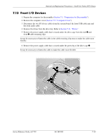
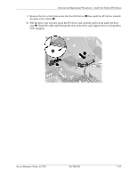
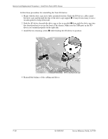
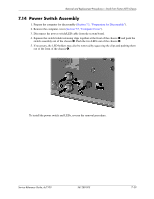
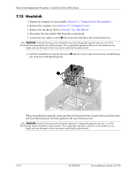
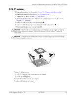
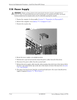
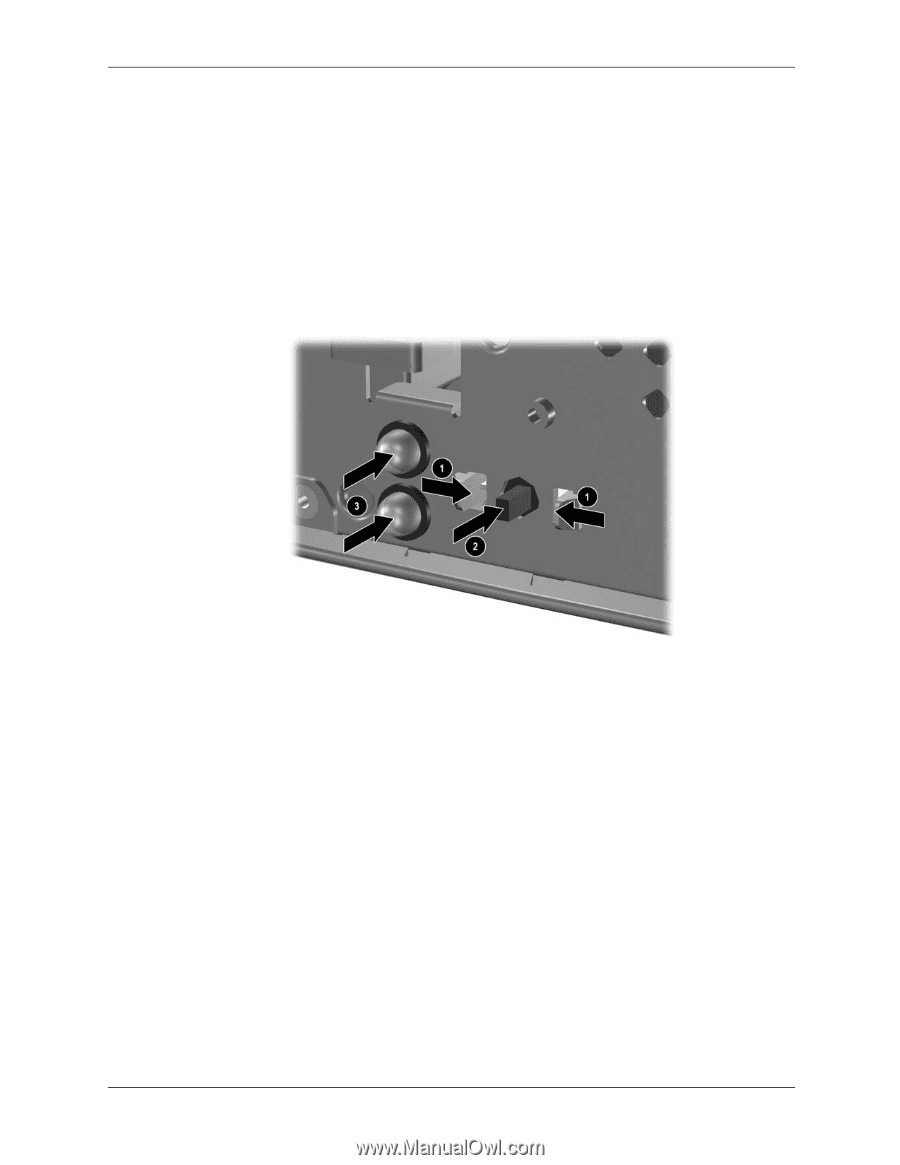
Removal and Replacement Procedures- Small Form Factor (SFF) Chassis 7.14 Power Switch Assembly 1. Prepare the computer for disassembly (Section 7.1, "Preparation for Disassembly"). 2. Remove the computer cover (Section 7.5, "Computer Cover"). 3. Disconnect the power switch/LED cable from the system board. 4. Squeeze the switch holder retaining clips together at the front of the chassis 1 and push the switch assembly out of the chassis 2. Push the two LEDs out of the chassis 3. 5. If necessary, the LED holders may also be removed by squeezing the clips and pushing them out of the front of the chassis 4. To install the power switch and LEDs, reverse the removal procedure. Service Reference Guide, dc7100 361288-003 7-39
-
 1
1 -
2
-
3
-
4
-
5
-
6
-
7
-
8
-
9
-
10
-
11
-
12
-
13
-
14
-
15
-
16
-
17
-
18
-
19
-
20
-
21
-
22
-
23
-
24
-
25
-
26
-
27
-
28
-
29
-
30
-
31
-
32
-
33
-
34
-
35
-
36
-
37
-
38
-
39
-
40
-
41
-
42
-
43
-
44
-
45
-
46
-
47
-
48
-
49
-
50
-
51
-
52
-
53
-
54
-
55
-
56
-
57
-
58
-
59
-
60
-
61
-
62
-
63
-
64
-
65
-
66
-
67
-
68
-
69
-
70
-
71
-
72
-
73
-
74
-
75
-
76
-
77
-
78
-
79
-
80
-
81
-
82
-
83
-
84
-
85
-
86
-
87
-
88
-
89
-
90
-
91
-
92
-
93
-
94
-
95
-
96
-
97
-
98
-
99
-
100
-
101
-
102
-
103
-
104
-
105
-
106
-
107
-
108
-
109
-
110
-
111
-
112
-
113
-
114
-
115
-
116
-
117
-
118
-
119
-
120
-
121
-
122
-
123
-
124
-
125
-
126
-
127
-
128
-
129
-
130
-
131
-
132
-
133
-
134
-
135
-
136
-
137
-
138
-
139
-
140
-
141
-
142
-
143
-
144
-
145
-
146
-
147
-
148
-
149
-
150
-
151
-
152
-
153
-
154
-
155
-
156
-
157
-
158
-
159
-
 160
160 -
 161
161 -
 162
162 -
 163
163 -
 164
164 -
 165
165 -
 166
166 -
 167
167 -
 168
168 -
 169
169 -
 170
170 -
171
-
172
-
173
-
174
-
175
-
176
-
177
-
178
-
179
-
180
-
181
-
182
-
183
-
184
-
185
-
186
-
187
-
188
-
189
-
190
-
191
-
192
-
193
-
194
-
195
-
196
-
197
-
198
-
199
-
200
-
201
-
202
-
203
-
204
-
205
-
206
-
207
-
208
-
209
-
210
-
211
-
212
-
213
-
214
-
215
-
216
-
217
-
218
-
219
-
220
-
221
-
222
-
223
-
224
-
225
-
226
-
227
-
228
-
229
-
230
-
231
-
232
-
233
-
234
-
235
-
236
-
237
-
238
-
239
-
240
-
241
-
242
-
243
-
244
-
245
-
246
-
247
-
248
-
249
-
250
-
251
-
252
-
253
-
254
-
255
-
256
-
257
-
258
-
259
-
260
-
261
-
262
-
263
-
264
-
265
-
266
-
267
-
268
-
269
-
270
-
271
-
272
-
273
-
274
-
275
-
276
-
277
-
278
-
279
-
280
-
281
-
282
-
283
-
284
-
285
-
286
-
287
-
288
-
289
-
290
 |
 |
Service Reference Guide, dc7100
361288-003
7–39
Removal and Replacement Procedures— Small Form Factor (SFF) Chassis
7.14 Power Switch Assembly
1. Prepare the computer for disassembly (
Section 7.1, “Preparation for Disassembly”
).
2. Remove the computer cover (
Section 7.5, “Computer Cover”
).
3. Disconnect the power switch/LED cable from the system board.
4. Squeeze the switch holder retaining clips together at the front of the chassis
1
and push the
switch assembly out of the chassis
2
. Push the two LEDs out of the chassis
3
.
5.
If necessary, the LED holders may also be removed by squeezing the clips and pushing them
out of the front of the chassis
4
.
To install the power switch and LEDs, reverse the removal procedure.