HP Dc7100 HP Compaq Business Desktop dc7100 Series Service Reference Guide, 3r - Page 151
Riser Card,
 |
UPC - 829160356877
View all HP Dc7100 manuals
Add to My Manuals
Save this manual to your list of manuals |
Page 151 highlights
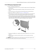
Removal and Replacement Procedures- Small Form Factor (SFF) Chassis 7.10.3 Riser Card 1. If you have locked the Smart Cover Lock, use Computer Setup to unlock the lock (Section 7.2, "Unlocking the Smart Cover Lock"). 2. Prepare the computer for disassembly (Section 7.1, "Preparation for Disassembly"). 3. Remove the computer access panel (Section 7.5, "Computer Cover"). 4. Remove the expansion card cage (Section 7.10.1, "Expansion Card Cage"). 5. Remove the two screws that secure the riser card to the expansion card cage 1, then remove the card 2. To install the riser card, reverse the removal procedure. ✎ The riser card is not spared separately at the time this document was released. Service Reference Guide, dc7100 361288-003 7-25
-
 1
1 -
2
-
3
-
4
-
5
-
6
-
7
-
8
-
9
-
10
-
11
-
12
-
13
-
14
-
15
-
16
-
17
-
18
-
19
-
20
-
21
-
22
-
23
-
24
-
25
-
26
-
27
-
28
-
29
-
30
-
31
-
32
-
33
-
34
-
35
-
36
-
37
-
38
-
39
-
40
-
41
-
42
-
43
-
44
-
45
-
46
-
47
-
48
-
49
-
50
-
51
-
52
-
53
-
54
-
55
-
56
-
57
-
58
-
59
-
60
-
61
-
62
-
63
-
64
-
65
-
66
-
67
-
68
-
69
-
70
-
71
-
72
-
73
-
74
-
75
-
76
-
77
-
78
-
79
-
80
-
81
-
82
-
83
-
84
-
85
-
86
-
87
-
88
-
89
-
90
-
91
-
92
-
93
-
94
-
95
-
96
-
97
-
98
-
99
-
100
-
101
-
102
-
103
-
104
-
105
-
106
-
107
-
108
-
109
-
110
-
111
-
112
-
113
-
114
-
115
-
116
-
117
-
118
-
119
-
120
-
121
-
122
-
123
-
124
-
125
-
126
-
127
-
128
-
129
-
130
-
131
-
132
-
133
-
134
-
135
-
136
-
137
-
138
-
139
-
140
-
141
-
142
-
143
-
144
-
145
-
 146
146 -
 147
147 -
 148
148 -
 149
149 -
 150
150 -
 151
151 -
 152
152 -
 153
153 -
 154
154 -
 155
155 -
 156
156 -
157
-
158
-
159
-
160
-
161
-
162
-
163
-
164
-
165
-
166
-
167
-
168
-
169
-
170
-
171
-
172
-
173
-
174
-
175
-
176
-
177
-
178
-
179
-
180
-
181
-
182
-
183
-
184
-
185
-
186
-
187
-
188
-
189
-
190
-
191
-
192
-
193
-
194
-
195
-
196
-
197
-
198
-
199
-
200
-
201
-
202
-
203
-
204
-
205
-
206
-
207
-
208
-
209
-
210
-
211
-
212
-
213
-
214
-
215
-
216
-
217
-
218
-
219
-
220
-
221
-
222
-
223
-
224
-
225
-
226
-
227
-
228
-
229
-
230
-
231
-
232
-
233
-
234
-
235
-
236
-
237
-
238
-
239
-
240
-
241
-
242
-
243
-
244
-
245
-
246
-
247
-
248
-
249
-
250
-
251
-
252
-
253
-
254
-
255
-
256
-
257
-
258
-
259
-
260
-
261
-
262
-
263
-
264
-
265
-
266
-
267
-
268
-
269
-
270
-
271
-
272
-
273
-
274
-
275
-
276
-
277
-
278
-
279
-
280
-
281
-
282
-
283
-
284
-
285
-
286
-
287
-
288
-
289
-
290
 |
 |
Service Reference Guide, dc7100
361288-003
7–25
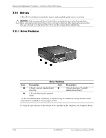
Removal and Replacement Procedures— Small Form Factor (SFF) Chassis
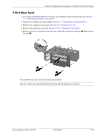
7.10.3 Riser Card
1. If you have locked the Smart Cover Lock, use Computer Setup to unlock the lock (
Section
7.2, “Unlocking the Smart Cover Lock”
).
2. Prepare the computer for disassembly (
Section 7.1, “Preparation for Disassembly”
).
3. Remove the computer access panel (
Section 7.5, “Computer Cover”
).
4. Remove the expansion card cage (
Section 7.10.1, “Expansion Card Cage”
).
5. Remove the two screws that secure the riser card to the expansion card cage
1
, then remove
the card
2
.
To install the riser card, reverse the removal procedure.
The riser card is not spared separately at the time this document was released.