HP Dc7100 HP Compaq Business Desktop dc7100 Series Service Reference Guide, 3r - Page 109
Power Switch Assembly, switch assembly out of the chassis
 |
UPC - 829160356877
View all HP Dc7100 manuals
Add to My Manuals
Save this manual to your list of manuals |
Page 109 highlights
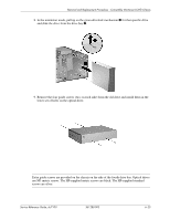
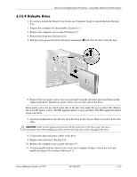
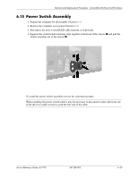
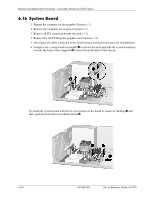
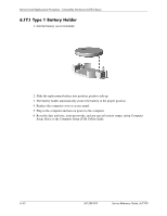
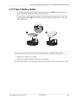
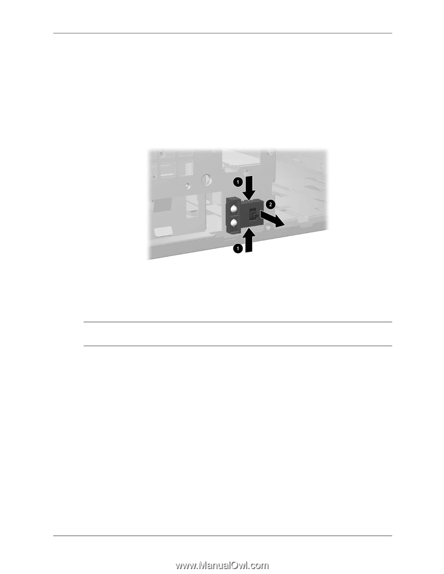
Removal and Replacement Procedures - Convertible Minitower (CMT) Chassis 6.15 Power Switch Assembly 1. Prepare the computer for disassembly (Section 6.1). 2. Remove the computer access panel (Section 6.5). 3. Disconnect the power switch/LED cable from the system board. 4. Squeeze the switch holder retaining clips together at the front of the chassis 1 and pull the switch assembly out of the chassis 2. To install the power switch assembly, reverse the removal procedure. ✎ When installing the power switch cable it may be necessary to disconnect a data cabe from one of the drives to make it easier to grab the free end of the cable. Service Reference Guide, dc7100 361288-003 6-29
-
 1
1 -
2
-
3
-
4
-
5
-
6
-
7
-
8
-
9
-
10
-
11
-
12
-
13
-
14
-
15
-
16
-
17
-
18
-
19
-
20
-
21
-
22
-
23
-
24
-
25
-
26
-
27
-
28
-
29
-
30
-
31
-
32
-
33
-
34
-
35
-
36
-
37
-
38
-
39
-
40
-
41
-
42
-
43
-
44
-
45
-
46
-
47
-
48
-
49
-
50
-
51
-
52
-
53
-
54
-
55
-
56
-
57
-
58
-
59
-
60
-
61
-
62
-
63
-
64
-
65
-
66
-
67
-
68
-
69
-
70
-
71
-
72
-
73
-
74
-
75
-
76
-
77
-
78
-
79
-
80
-
81
-
82
-
83
-
84
-
85
-
86
-
87
-
88
-
89
-
90
-
91
-
92
-
93
-
94
-
95
-
96
-
97
-
98
-
99
-
100
-
101
-
102
-
103
-
 104
104 -
 105
105 -
 106
106 -
 107
107 -
 108
108 -
 109
109 -
 110
110 -
 111
111 -
 112
112 -
 113
113 -
 114
114 -
115
-
116
-
117
-
118
-
119
-
120
-
121
-
122
-
123
-
124
-
125
-
126
-
127
-
128
-
129
-
130
-
131
-
132
-
133
-
134
-
135
-
136
-
137
-
138
-
139
-
140
-
141
-
142
-
143
-
144
-
145
-
146
-
147
-
148
-
149
-
150
-
151
-
152
-
153
-
154
-
155
-
156
-
157
-
158
-
159
-
160
-
161
-
162
-
163
-
164
-
165
-
166
-
167
-
168
-
169
-
170
-
171
-
172
-
173
-
174
-
175
-
176
-
177
-
178
-
179
-
180
-
181
-
182
-
183
-
184
-
185
-
186
-
187
-
188
-
189
-
190
-
191
-
192
-
193
-
194
-
195
-
196
-
197
-
198
-
199
-
200
-
201
-
202
-
203
-
204
-
205
-
206
-
207
-
208
-
209
-
210
-
211
-
212
-
213
-
214
-
215
-
216
-
217
-
218
-
219
-
220
-
221
-
222
-
223
-
224
-
225
-
226
-
227
-
228
-
229
-
230
-
231
-
232
-
233
-
234
-
235
-
236
-
237
-
238
-
239
-
240
-
241
-
242
-
243
-
244
-
245
-
246
-
247
-
248
-
249
-
250
-
251
-
252
-
253
-
254
-
255
-
256
-
257
-
258
-
259
-
260
-
261
-
262
-
263
-
264
-
265
-
266
-
267
-
268
-
269
-
270
-
271
-
272
-
273
-
274
-
275
-
276
-
277
-
278
-
279
-
280
-
281
-
282
-
283
-
284
-
285
-
286
-
287
-
288
-
289
-
290
 |
 |
Service Reference Guide, dc7100
361288-003
6–29
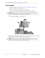
Removal and Replacement Procedures - Convertible Minitower (CMT) Chassis
6.15 Power Switch Assembly
1. Prepare the computer for disassembly (Section
6.1
).
2. Remove the computer access panel (Section
6.5
).
3. Disconnect the power switch/LED cable from the system board.
4. Squeeze the switch holder retaining clips together at the front of the chassis
1
and pull the
switch assembly out of the chassis
2
.
To install the power switch assembly, reverse the removal procedure.
When installing the power switch cable it may be necessary to disconnect a data cabe from one
of the drives to make it easier to grab the free end of the cable.