HP Dc7100 HP Compaq Business Desktop dc7100 Series Service Reference Guide, 3r - Page 214
Power Supply
 |
UPC - 829160356877
View all HP Dc7100 manuals
Add to My Manuals
Save this manual to your list of manuals |
Page 214 highlights
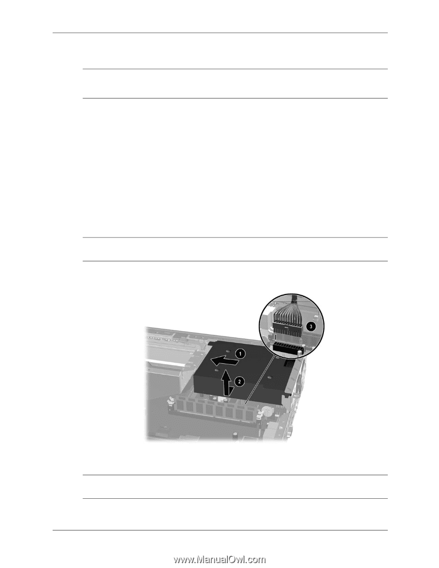
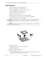
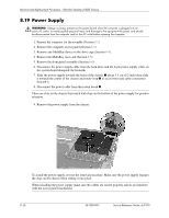
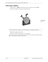
Removal and Replacement Procedures - Ultra-Slim Desktop (USDT) Chassis 8.19 Power Supply Å WARNING: Voltage is always present on the system board when the computer is plugged into an active AC outlet. To avoid possible personal injury and damage to the equipment the power cord should be disconnected from the computer and/or the AC outlet before opening the computer. 1. Prepare the computer for disassembly (Section 8.1). 2. Remove the computer access panel (Section 8.3). 3. Remove any MultiBay device in the drive cage (Section 8.4). 4. Remove the MultiBay riser card (Section 8.5). 5. Remove the front panel assembly (Section 8.6). 6. Disconnect the power supply cable from the hard drive and the 6-pin power supply cable on the system board alongside the heatsink. 7. Slide the power supply towards the front of the chassis 1 about 1.3 cm (1/2 inch) then slide it towards the center of the chassis and rotate it up 2 to access the main cable connection beneath it. 8. Disconnect the power cable from thesystem board 3. ✎ There are slots on the chassis that match with clips on the bottom of the power supply for positive retention. 9. Remove the power supply from the chassis. To install the power supply, reverse the removal procedure. Make sure the power supply engages the clips on the chassis when sliding it into place. ✎ When installing the power supply make sure the cables are routed properly and do not interfere with the access panel installation. 8-26 361288-003 Service Reference Guide, dc7100
-
 1
1 -
2
-
3
-
4
-
5
-
6
-
7
-
8
-
9
-
10
-
11
-
12
-
13
-
14
-
15
-
16
-
17
-
18
-
19
-
20
-
21
-
22
-
23
-
24
-
25
-
26
-
27
-
28
-
29
-
30
-
31
-
32
-
33
-
34
-
35
-
36
-
37
-
38
-
39
-
40
-
41
-
42
-
43
-
44
-
45
-
46
-
47
-
48
-
49
-
50
-
51
-
52
-
53
-
54
-
55
-
56
-
57
-
58
-
59
-
60
-
61
-
62
-
63
-
64
-
65
-
66
-
67
-
68
-
69
-
70
-
71
-
72
-
73
-
74
-
75
-
76
-
77
-
78
-
79
-
80
-
81
-
82
-
83
-
84
-
85
-
86
-
87
-
88
-
89
-
90
-
91
-
92
-
93
-
94
-
95
-
96
-
97
-
98
-
99
-
100
-
101
-
102
-
103
-
104
-
105
-
106
-
107
-
108
-
109
-
110
-
111
-
112
-
113
-
114
-
115
-
116
-
117
-
118
-
119
-
120
-
121
-
122
-
123
-
124
-
125
-
126
-
127
-
128
-
129
-
130
-
131
-
132
-
133
-
134
-
135
-
136
-
137
-
138
-
139
-
140
-
141
-
142
-
143
-
144
-
145
-
146
-
147
-
148
-
149
-
150
-
151
-
152
-
153
-
154
-
155
-
156
-
157
-
158
-
159
-
160
-
161
-
162
-
163
-
164
-
165
-
166
-
167
-
168
-
169
-
170
-
171
-
172
-
173
-
174
-
175
-
176
-
177
-
178
-
179
-
180
-
181
-
182
-
183
-
184
-
185
-
186
-
187
-
188
-
189
-
190
-
191
-
192
-
193
-
194
-
195
-
196
-
197
-
198
-
199
-
200
-
201
-
202
-
203
-
204
-
205
-
206
-
207
-
208
-
 209
209 -
 210
210 -
 211
211 -
 212
212 -
 213
213 -
 214
214 -
 215
215 -
 216
216 -
 217
217 -
 218
218 -
 219
219 -
220
-
221
-
222
-
223
-
224
-
225
-
226
-
227
-
228
-
229
-
230
-
231
-
232
-
233
-
234
-
235
-
236
-
237
-
238
-
239
-
240
-
241
-
242
-
243
-
244
-
245
-
246
-
247
-
248
-
249
-
250
-
251
-
252
-
253
-
254
-
255
-
256
-
257
-
258
-
259
-
260
-
261
-
262
-
263
-
264
-
265
-
266
-
267
-
268
-
269
-
270
-
271
-
272
-
273
-
274
-
275
-
276
-
277
-
278
-
279
-
280
-
281
-
282
-
283
-
284
-
285
-
286
-
287
-
288
-
289
-
290
 |
 |