HP Dc7100 HP Compaq Business Desktop dc7100 Series Service Reference Guide, 3r - Page 196
Front Panel Assembly, Disconnect the fan cable from the system board
 |
UPC - 829160356877
View all HP Dc7100 manuals
Add to My Manuals
Save this manual to your list of manuals |
Page 196 highlights
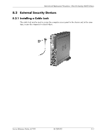
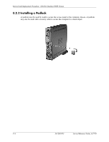
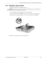
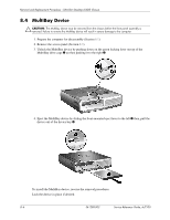
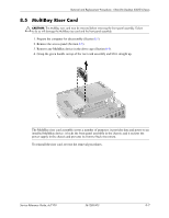
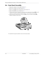
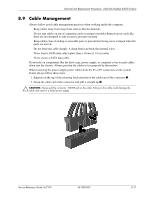
Removal and Replacement Procedures - Ultra-Slim Desktop (USDT) Chassis 8.6 Front Panel Assembly 1. Prepare the computer for disassembly (Section 8.1). 2. Remove the computer access panel (Section 8.3). 3. Remove any MultiBay device from the drive cage (Section 8.4). 4. Remove the MultiBay riser card (Section 8.5). 5. Lift up on the two green locking levers release tabs on the right side of the bezel 1. This will unlatch the front panel assembly and push it about 1.3 cm (1/2 inch) out of the chassis. 6. Disconnect the fan cable from the system board 2 and remove the panel assembly 3 by pulling it straight out of the chassis. To reinstall the front panel assembly, reverse the removal procedure. 8-8 361288-003 Service Reference Guide, dc7100
-
 1
1 -
2
-
3
-
4
-
5
-
6
-
7
-
8
-
9
-
10
-
11
-
12
-
13
-
14
-
15
-
16
-
17
-
18
-
19
-
20
-
21
-
22
-
23
-
24
-
25
-
26
-
27
-
28
-
29
-
30
-
31
-
32
-
33
-
34
-
35
-
36
-
37
-
38
-
39
-
40
-
41
-
42
-
43
-
44
-
45
-
46
-
47
-
48
-
49
-
50
-
51
-
52
-
53
-
54
-
55
-
56
-
57
-
58
-
59
-
60
-
61
-
62
-
63
-
64
-
65
-
66
-
67
-
68
-
69
-
70
-
71
-
72
-
73
-
74
-
75
-
76
-
77
-
78
-
79
-
80
-
81
-
82
-
83
-
84
-
85
-
86
-
87
-
88
-
89
-
90
-
91
-
92
-
93
-
94
-
95
-
96
-
97
-
98
-
99
-
100
-
101
-
102
-
103
-
104
-
105
-
106
-
107
-
108
-
109
-
110
-
111
-
112
-
113
-
114
-
115
-
116
-
117
-
118
-
119
-
120
-
121
-
122
-
123
-
124
-
125
-
126
-
127
-
128
-
129
-
130
-
131
-
132
-
133
-
134
-
135
-
136
-
137
-
138
-
139
-
140
-
141
-
142
-
143
-
144
-
145
-
146
-
147
-
148
-
149
-
150
-
151
-
152
-
153
-
154
-
155
-
156
-
157
-
158
-
159
-
160
-
161
-
162
-
163
-
164
-
165
-
166
-
167
-
168
-
169
-
170
-
171
-
172
-
173
-
174
-
175
-
176
-
177
-
178
-
179
-
180
-
181
-
182
-
183
-
184
-
185
-
186
-
187
-
188
-
189
-
190
-
 191
191 -
 192
192 -
 193
193 -
 194
194 -
 195
195 -
 196
196 -
 197
197 -
 198
198 -
 199
199 -
 200
200 -
 201
201 -
202
-
203
-
204
-
205
-
206
-
207
-
208
-
209
-
210
-
211
-
212
-
213
-
214
-
215
-
216
-
217
-
218
-
219
-
220
-
221
-
222
-
223
-
224
-
225
-
226
-
227
-
228
-
229
-
230
-
231
-
232
-
233
-
234
-
235
-
236
-
237
-
238
-
239
-
240
-
241
-
242
-
243
-
244
-
245
-
246
-
247
-
248
-
249
-
250
-
251
-
252
-
253
-
254
-
255
-
256
-
257
-
258
-
259
-
260
-
261
-
262
-
263
-
264
-
265
-
266
-
267
-
268
-
269
-
270
-
271
-
272
-
273
-
274
-
275
-
276
-
277
-
278
-
279
-
280
-
281
-
282
-
283
-
284
-
285
-
286
-
287
-
288
-
289
-
290
 |
 |
8–8
361288-003
Service Reference Guide, dc7100
Removal and Replacement Procedures - Ultra-Slim Desktop (USDT) Chassis
8.6 Front Panel Assembly
1. Prepare the computer for disassembly (Section
8.1
).
2. Remove the computer access panel (Section
8.3
).
3. Remove any MultiBay device from the drive cage (Section
8.4
).
4. Remove the MultiBay riser card (Section
8.5
).
5.
Lift up on the two green locking levers release tabs on the right side of the bezel
1
. This will
unlatch the front panel assembly and push it about 1.3 cm (1/2 inch) out of the chassis.
6. Disconnect the fan cable from the system board
2
and remove the panel assembly
3
by
pulling it straight out of the chassis.
To reinstall the front panel assembly, reverse the removal procedure.