HP Dc7100 HP Compaq Business Desktop dc7100 Series Service Reference Guide, 3r - Page 166
Heatsink, Preparation for Disassembly, Computer Cover, Fan Shroud
 |
UPC - 829160356877
View all HP Dc7100 manuals
Add to My Manuals
Save this manual to your list of manuals |
Page 166 highlights
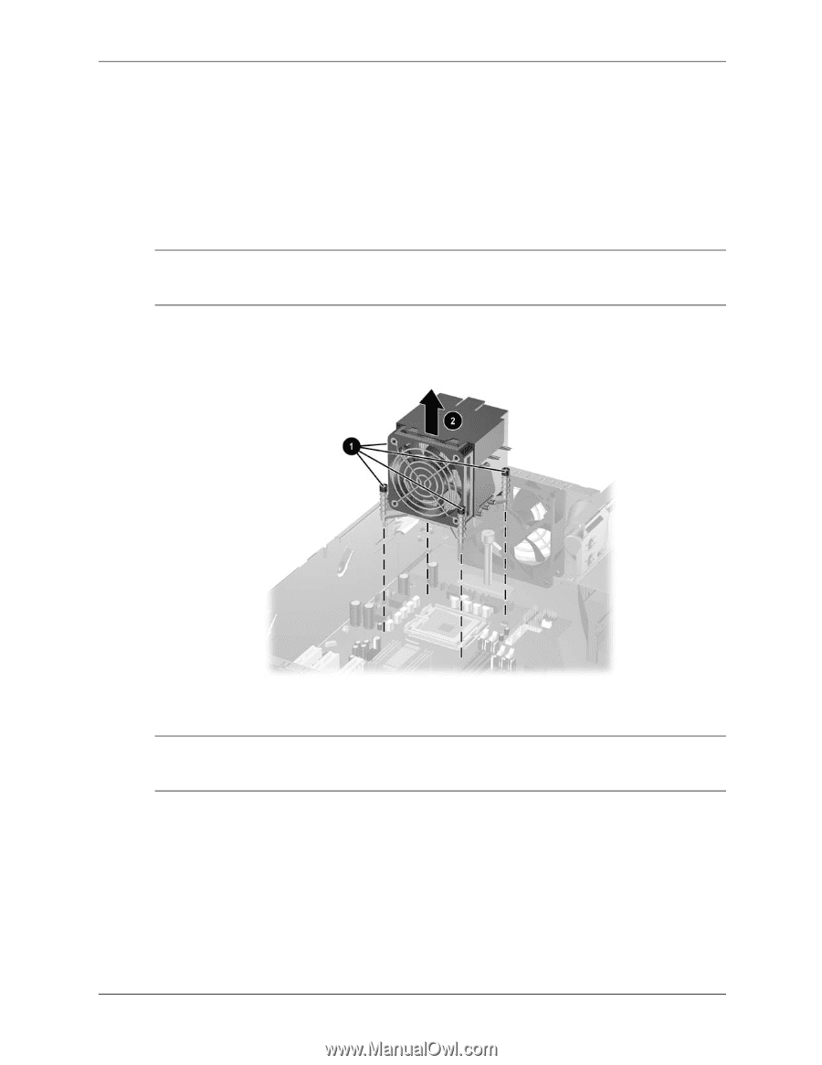
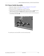
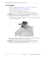
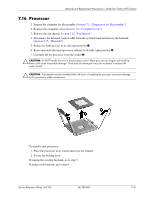
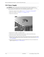
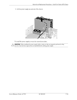
Removal and Replacement Procedures- Small Form Factor (SFF) Chassis 7.15 Heatsink 1. Prepare the computer for disassembly (Section 7.1, "Preparation for Disassembly"). 2. Remove the computer cover (Section 7.5, "Computer Cover"). 3. Remove the fan shroud. Refer to Section 7.12, "Fan Shroud". 4. Disconnect the fan control cable from the system board. 5. Loosen the four captive screws 1 that secure the heatsink to the system board tray. Ä CAUTION: Heatsink retaining screws should be removed in diagonally opposite pairs (as in an X) to even the downward forces on the processor. This is especially important as the pins on the socket are very fragile and any damage to them may require replacing the system board. 6. Lift the heatsink from atop the processor 2 and set is on its side to keep from contaminating the work area with thermal grease. When reinstalling the heatsink, make sure that its bottom has been cleaned with an alcohol wipe and fresh thermal grease has been applied to the top of the processor. Ä CAUTION: Heatsink retaining screws should be tightened in diagonally opposite pairs (as in an X) to evenly seat the heatsink on the processor. This is especially important as the pins on the socket are very fragile and any damage to them may require replacing the system board. 7-40 361288-003 Service Reference Guide, dc7100
-
 1
1 -
2
-
3
-
4
-
5
-
6
-
7
-
8
-
9
-
10
-
11
-
12
-
13
-
14
-
15
-
16
-
17
-
18
-
19
-
20
-
21
-
22
-
23
-
24
-
25
-
26
-
27
-
28
-
29
-
30
-
31
-
32
-
33
-
34
-
35
-
36
-
37
-
38
-
39
-
40
-
41
-
42
-
43
-
44
-
45
-
46
-
47
-
48
-
49
-
50
-
51
-
52
-
53
-
54
-
55
-
56
-
57
-
58
-
59
-
60
-
61
-
62
-
63
-
64
-
65
-
66
-
67
-
68
-
69
-
70
-
71
-
72
-
73
-
74
-
75
-
76
-
77
-
78
-
79
-
80
-
81
-
82
-
83
-
84
-
85
-
86
-
87
-
88
-
89
-
90
-
91
-
92
-
93
-
94
-
95
-
96
-
97
-
98
-
99
-
100
-
101
-
102
-
103
-
104
-
105
-
106
-
107
-
108
-
109
-
110
-
111
-
112
-
113
-
114
-
115
-
116
-
117
-
118
-
119
-
120
-
121
-
122
-
123
-
124
-
125
-
126
-
127
-
128
-
129
-
130
-
131
-
132
-
133
-
134
-
135
-
136
-
137
-
138
-
139
-
140
-
141
-
142
-
143
-
144
-
145
-
146
-
147
-
148
-
149
-
150
-
151
-
152
-
153
-
154
-
155
-
156
-
157
-
158
-
159
-
160
-
 161
161 -
 162
162 -
 163
163 -
 164
164 -
 165
165 -
 166
166 -
 167
167 -
 168
168 -
 169
169 -
 170
170 -
 171
171 -
172
-
173
-
174
-
175
-
176
-
177
-
178
-
179
-
180
-
181
-
182
-
183
-
184
-
185
-
186
-
187
-
188
-
189
-
190
-
191
-
192
-
193
-
194
-
195
-
196
-
197
-
198
-
199
-
200
-
201
-
202
-
203
-
204
-
205
-
206
-
207
-
208
-
209
-
210
-
211
-
212
-
213
-
214
-
215
-
216
-
217
-
218
-
219
-
220
-
221
-
222
-
223
-
224
-
225
-
226
-
227
-
228
-
229
-
230
-
231
-
232
-
233
-
234
-
235
-
236
-
237
-
238
-
239
-
240
-
241
-
242
-
243
-
244
-
245
-
246
-
247
-
248
-
249
-
250
-
251
-
252
-
253
-
254
-
255
-
256
-
257
-
258
-
259
-
260
-
261
-
262
-
263
-
264
-
265
-
266
-
267
-
268
-
269
-
270
-
271
-
272
-
273
-
274
-
275
-
276
-
277
-
278
-
279
-
280
-
281
-
282
-
283
-
284
-
285
-
286
-
287
-
288
-
289
-
290
 |
 |