HP Dc7100 HP Compaq Business Desktop dc7100 Series Service Reference Guide, 3r - Page 180
the system board.
 |
UPC - 829160356877
View all HP Dc7100 manuals
Add to My Manuals
Save this manual to your list of manuals |
Page 180 highlights
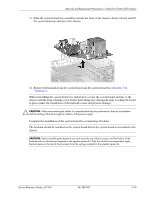
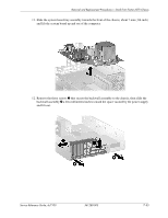
Removal and Replacement Procedures- Small Form Factor (SFF) Chassis 13. Slide the new backwall 1 onto the rear chassis. Secure it with the three screws 2 removed from the old backwall. 14. Install the serial connector 1 into the new backwall using the two screws 2 that were removed from the serial connector in a previous step. Reconnect the "Serial A" cable 3 to the system board. 15. Install the system board tray assembly. Be sure the keyhole slot on the system board sits properly over the locking pins. When the system board is in position, replace the long screw to secure the system board to the chassis. 7-54 361288-003 Service Reference Guide, dc7100
-
 1
1 -
2
-
3
-
4
-
5
-
6
-
7
-
8
-
9
-
10
-
11
-
12
-
13
-
14
-
15
-
16
-
17
-
18
-
19
-
20
-
21
-
22
-
23
-
24
-
25
-
26
-
27
-
28
-
29
-
30
-
31
-
32
-
33
-
34
-
35
-
36
-
37
-
38
-
39
-
40
-
41
-
42
-
43
-
44
-
45
-
46
-
47
-
48
-
49
-
50
-
51
-
52
-
53
-
54
-
55
-
56
-
57
-
58
-
59
-
60
-
61
-
62
-
63
-
64
-
65
-
66
-
67
-
68
-
69
-
70
-
71
-
72
-
73
-
74
-
75
-
76
-
77
-
78
-
79
-
80
-
81
-
82
-
83
-
84
-
85
-
86
-
87
-
88
-
89
-
90
-
91
-
92
-
93
-
94
-
95
-
96
-
97
-
98
-
99
-
100
-
101
-
102
-
103
-
104
-
105
-
106
-
107
-
108
-
109
-
110
-
111
-
112
-
113
-
114
-
115
-
116
-
117
-
118
-
119
-
120
-
121
-
122
-
123
-
124
-
125
-
126
-
127
-
128
-
129
-
130
-
131
-
132
-
133
-
134
-
135
-
136
-
137
-
138
-
139
-
140
-
141
-
142
-
143
-
144
-
145
-
146
-
147
-
148
-
149
-
150
-
151
-
152
-
153
-
154
-
155
-
156
-
157
-
158
-
159
-
160
-
161
-
162
-
163
-
164
-
165
-
166
-
167
-
168
-
169
-
170
-
171
-
172
-
173
-
174
-
 175
175 -
 176
176 -
 177
177 -
 178
178 -
 179
179 -
 180
180 -
 181
181 -
 182
182 -
 183
183 -
 184
184 -
 185
185 -
186
-
187
-
188
-
189
-
190
-
191
-
192
-
193
-
194
-
195
-
196
-
197
-
198
-
199
-
200
-
201
-
202
-
203
-
204
-
205
-
206
-
207
-
208
-
209
-
210
-
211
-
212
-
213
-
214
-
215
-
216
-
217
-
218
-
219
-
220
-
221
-
222
-
223
-
224
-
225
-
226
-
227
-
228
-
229
-
230
-
231
-
232
-
233
-
234
-
235
-
236
-
237
-
238
-
239
-
240
-
241
-
242
-
243
-
244
-
245
-
246
-
247
-
248
-
249
-
250
-
251
-
252
-
253
-
254
-
255
-
256
-
257
-
258
-
259
-
260
-
261
-
262
-
263
-
264
-
265
-
266
-
267
-
268
-
269
-
270
-
271
-
272
-
273
-
274
-
275
-
276
-
277
-
278
-
279
-
280
-
281
-
282
-
283
-
284
-
285
-
286
-
287
-
288
-
289
-
290
 |
 |

7–54
361288-003
Service Reference Guide, dc7100
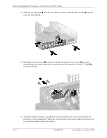
Removal and Replacement Procedures— Small Form Factor (SFF) Chassis
13. Slide the new backwall
1
onto the rear chassis. Secure it with the three screws
2
removed
from the old backwall.
14. Install the serial connector
1
into the new backwall using the two screws
2
that were
removed from the serial connector in a previous step. Reconnect the “Serial A” cable
3
to
the system board.
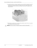
15. Install the system board tray assembly. Be sure the keyhole slot on the system board sits
properly over the locking pins. When the system board is in position, replace the long screw
to secure the system board to the chassis.