Sharp MX-M363N Installation Manual - Page 102
DH POWER, 120V Series
 |
View all Sharp MX-M363N manuals
Add to My Manuals
Save this manual to your list of manuals |
Page 102 highlights
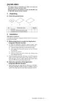
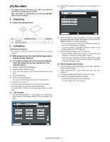
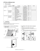
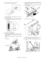
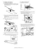
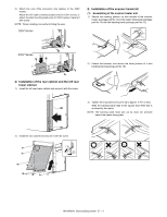
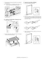
2) Cut the switch part of the left rear lower cabinet. NOTE: Be careful not to damage the cabinet. 2) Remove the snap band. Insert the supporter (package part No. 3) to the frame of the power unit, and attach the WH PWB (package part No. 4) on it. NOTE: Be careful not to break the PWB when mounting the PWB to the supporters. 3) Attach the label for heater switch (package part No. 2) to the left rear lower cabinet. NOTE: Wipe the surface where the label is to be affixed with alcohol, then attach the label along the concave on left rear lower cabinet. 3) Connect the harness to the WH PWB. DH POWER (2) Installation of the WH PWB 1) Remove the screw, and remove the AC-cable connection plate (only for 120V series), or remove the inlet mounting plate (only for 230V series). Remove the core (This procedure only applies to the 230V series). 120V Series 4) Connect the AC-WH harness 1 (package part No. 5) to the AC PWB, the WH PWB and the dehumidifier heater switch. NOTE: The AC-WH harness 1 should pass under the MSW harness. 230V Series MX-M503N Dehumidifying heater 27 - 2
-
 1
1 -
2
-
3
-
4
-
5
-
6
-
7
-
8
-
9
-
10
-
11
-
12
-
13
-
14
-
15
-
16
-
17
-
18
-
19
-
20
-
21
-
22
-
23
-
24
-
25
-
26
-
27
-
28
-
29
-
30
-
31
-
32
-
33
-
34
-
35
-
36
-
37
-
38
-
39
-
40
-
41
-
42
-
43
-
44
-
45
-
46
-
47
-
48
-
49
-
50
-
51
-
52
-
53
-
54
-
55
-
56
-
57
-
58
-
59
-
60
-
61
-
62
-
63
-
64
-
65
-
66
-
67
-
68
-
69
-
70
-
71
-
72
-
73
-
74
-
75
-
76
-
77
-
78
-
79
-
80
-
81
-
82
-
83
-
84
-
85
-
86
-
87
-
88
-
89
-
90
-
91
-
92
-
93
-
94
-
95
-
96
-
 97
97 -
 98
98 -
 99
99 -
 100
100 -
 101
101 -
 102
102 -
 103
103 -
 104
104 -
 105
105 -
 106
106 -
 107
107 -
108
-
109
-
110
-
111
-
112
-
113
-
114
-
115
-
116
-
117
 |
 |
