Sharp MX-M363N Installation Manual - Page 22
C. Height adjustment of the large capacity tray unit
 |
View all Sharp MX-M363N manuals
Add to My Manuals
Save this manual to your list of manuals |
Page 22 highlights
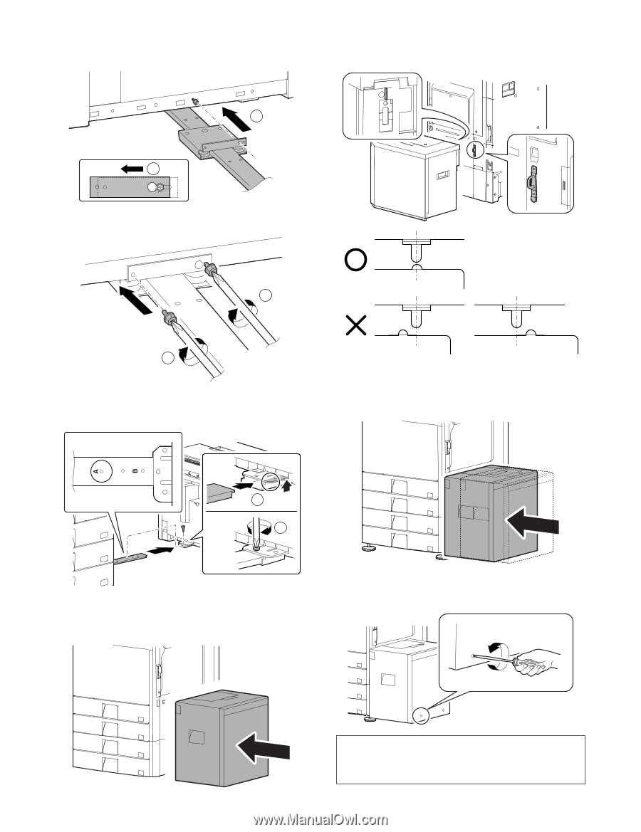
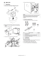
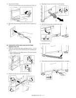
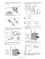
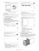
7) Insert the temporarily fixed screw B into the key hole in the connection unit (package part No. 2), and temporarily fix the connection unit. 2) Check to insure that the height adjustment check rib of the large capacity tray unit and the axis line of the mounting plate upper mounted to the main unit are in the same line. 1 2 8) Fix the other fixing screw B (package part No. 4), and tighten the temporarily fixed screw B securely. 2 1 9) While lifting the section marked with {, insert the connection unit into the large capacity tray unit, and fix the fixing screw C (package part No. 5) at the mark A on the connection unit. [Shift to the left] [Shift to the right] 3) If the height adjustment is not required, insert the large capacity tray unit further more. If the height adjustment is required, perform the adjustment procedures from 4). 1 2 C. Height adjustment of the large capacity tray unit 1) Put the large capacity tray unit closer to the main unit. 4) Loosen the adjustment screw on the F side. * Use the adjustment screw on the front side for the adjustment. Do not touch the screw on the rear side. NOTE: If the screw is loosened or removed when servicing, be sure to execute "C. Height adjustment of the large capacity tray unit" after completion of servicing. MX-M503N MX-LCX1 3 - 3
-
 1
1 -
2
-
3
-
4
-
5
-
6
-
7
-
8
-
9
-
10
-
11
-
12
-
13
-
14
-
15
-
16
-
 17
17 -
 18
18 -
 19
19 -
 20
20 -
 21
21 -
 22
22 -
 23
23 -
 24
24 -
 25
25 -
 26
26 -
 27
27 -
28
-
29
-
30
-
31
-
32
-
33
-
34
-
35
-
36
-
37
-
38
-
39
-
40
-
41
-
42
-
43
-
44
-
45
-
46
-
47
-
48
-
49
-
50
-
51
-
52
-
53
-
54
-
55
-
56
-
57
-
58
-
59
-
60
-
61
-
62
-
63
-
64
-
65
-
66
-
67
-
68
-
69
-
70
-
71
-
72
-
73
-
74
-
75
-
76
-
77
-
78
-
79
-
80
-
81
-
82
-
83
-
84
-
85
-
86
-
87
-
88
-
89
-
90
-
91
-
92
-
93
-
94
-
95
-
96
-
97
-
98
-
99
-
100
-
101
-
102
-
103
-
104
-
105
-
106
-
107
-
108
-
109
-
110
-
111
-
112
-
113
-
114
-
115
-
116
-
117
 |
 |