Sharp MX-M363N Installation Manual - Page 26
F. Turn on the power of the main unit, Auxiliary guide size switch, Rear edge shaft switch
 |
View all Sharp MX-M363N manuals
Add to My Manuals
Save this manual to your list of manuals |
Page 26 highlights
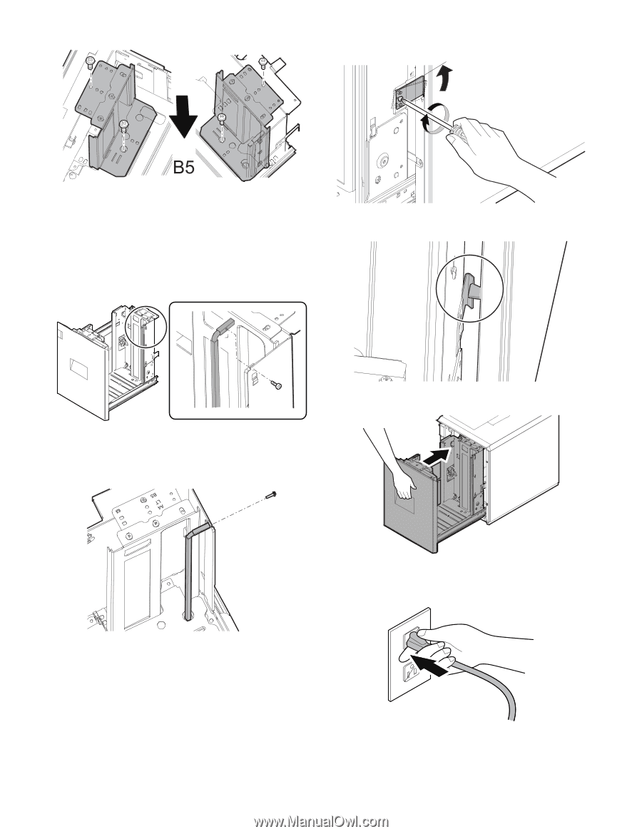
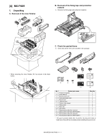
F side R side 3) Slightly push the tray, restore the stopper to the original position, and fix the fixing screw. b. Auxiliary guide size switch * Since the auxiliary guide setting is not required, fix the auxiliary guide to either of A4 or LT. (To prevent against missing of the part) c. Rear edge shaft switch 1) Remove the rear edge shift fixing screw (blue screw) which is fixing the shaft to the right side inside the tray, and remove the rear edge shaft. At that time, check to insure that the stopper pawl is engaged with the stopper reception of the large capacity tray unit. 4) Slowly insert the tray to the original position. 2) Insert the removed rear edge shaft into the mounting hole in the paper feed desk as shown in the figure below. Fix the upper section with the fixing screw (blue screw) which was removed previously. F. Turn on the power of the main unit 1) Insert the power plug of the main unit into the power outlet. NOTE: When the rear edge shaft is switched to B5, check to confirm that the side plates F/R are already set to B5. If the side plates F/R are not set to B5, the rear edge shaft cannot be switched to B5. MX-M503N MX-LCX1 3 - 7
-
 1
1 -
2
-
3
-
4
-
5
-
6
-
7
-
8
-
9
-
10
-
11
-
12
-
13
-
14
-
15
-
16
-
17
-
18
-
19
-
20
-
 21
21 -
 22
22 -
 23
23 -
 24
24 -
 25
25 -
 26
26 -
 27
27 -
 28
28 -
 29
29 -
 30
30 -
 31
31 -
32
-
33
-
34
-
35
-
36
-
37
-
38
-
39
-
40
-
41
-
42
-
43
-
44
-
45
-
46
-
47
-
48
-
49
-
50
-
51
-
52
-
53
-
54
-
55
-
56
-
57
-
58
-
59
-
60
-
61
-
62
-
63
-
64
-
65
-
66
-
67
-
68
-
69
-
70
-
71
-
72
-
73
-
74
-
75
-
76
-
77
-
78
-
79
-
80
-
81
-
82
-
83
-
84
-
85
-
86
-
87
-
88
-
89
-
90
-
91
-
92
-
93
-
94
-
95
-
96
-
97
-
98
-
99
-
100
-
101
-
102
-
103
-
104
-
105
-
106
-
107
-
108
-
109
-
110
-
111
-
112
-
113
-
114
-
115
-
116
-
117
 |
 |