Sharp MX-M363N Installation Manual - Page 69
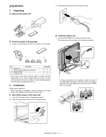
D. Attach the FAX memory., E. Attach the interface cable.
 |
View all Sharp MX-M363N manuals
Add to My Manuals
Save this manual to your list of manuals |
Page 69 highlights
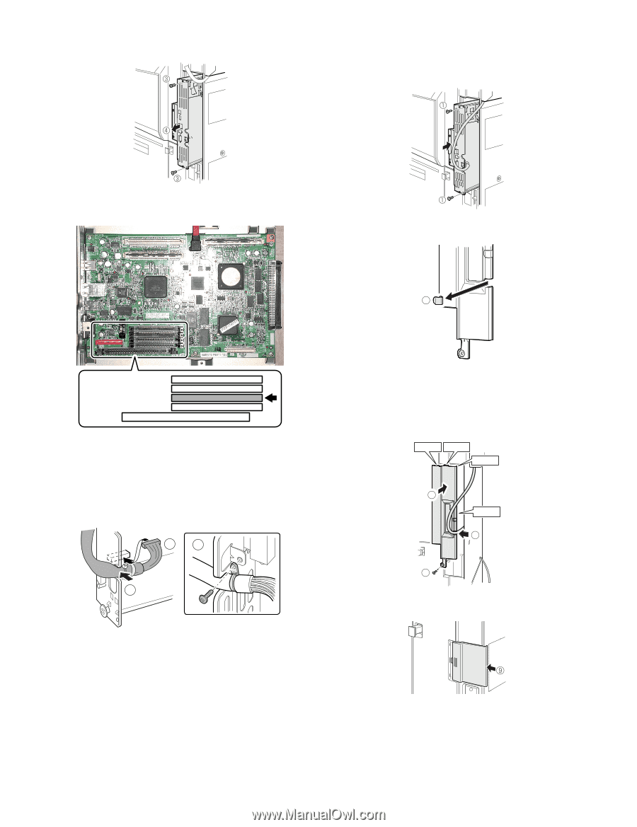
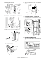
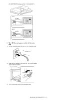
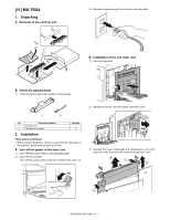
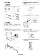
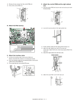
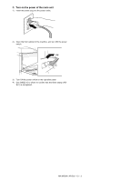
3) Remove the two screws from the control PWB unit. 4) Pull out the control PWB unit. F. Attach the control PWB and the right cabinet rear. 1) Push the control PWB unit into the main unit and secure it with the two screws. D. Attach the FAX memory. 2) Cut out the cut-out portion of the right cabinet rear. 2 PROG1 PROG2 FAX IMG EXT PCL/BARCODE PS KANJI E. Attach the interface cable. 1) Connect the interface cable to the control PWB unit. [Note] Check that the connector is not obliquely inserted. 2) Push the interface cable into the recessed portion of the sheet metal on the control PWB unit. 3) Fix a snap band with the bundled M3 screw. 13 2 3) Fit the interface cable into the opening that has been cut. 4) Attach the right cabinet rear cover to the main unit. At this time, check that the four hooks are properly fitted to the main unit. 5) Secure the right cabinet rear with the screw. Hook 1 Hook 2 Hook 3 4 Hook 4 3 5 6) Attach the ozone filter cover to the main unit. MX-M503N MX-FXX2 12 - 2
-
 1
1 -
2
-
3
-
4
-
5
-
6
-
7
-
8
-
9
-
10
-
11
-
12
-
13
-
14
-
15
-
16
-
17
-
18
-
19
-
20
-
21
-
22
-
23
-
24
-
25
-
26
-
27
-
28
-
29
-
30
-
31
-
32
-
33
-
34
-
35
-
36
-
37
-
38
-
39
-
40
-
41
-
42
-
43
-
44
-
45
-
46
-
47
-
48
-
49
-
50
-
51
-
52
-
53
-
54
-
55
-
56
-
57
-
58
-
59
-
60
-
61
-
62
-
63
-
 64
64 -
 65
65 -
 66
66 -
 67
67 -
 68
68 -
 69
69 -
 70
70 -
 71
71 -
 72
72 -
 73
73 -
 74
74 -
75
-
76
-
77
-
78
-
79
-
80
-
81
-
82
-
83
-
84
-
85
-
86
-
87
-
88
-
89
-
90
-
91
-
92
-
93
-
94
-
95
-
96
-
97
-
98
-
99
-
100
-
101
-
102
-
103
-
104
-
105
-
106
-
107
-
108
-
109
-
110
-
111
-
112
-
113
-
114
-
115
-
116
-
117
 |
 |