Sharp MX-M363N Installation Manual - Page 108
screw M5 x 16 package part No. 4., Raise the RSPF unit upright, and fix it with the accessory
 |
View all Sharp MX-M363N manuals
Add to My Manuals
Save this manual to your list of manuals |
Page 108 highlights
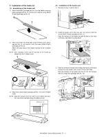
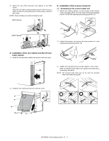
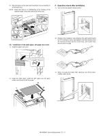
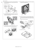
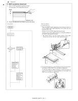
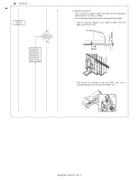
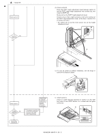
1 : '10/Jun/18 1 2) Cut the screw hole in the cabinet, and install the SPF step screw R (a) (package part No. 3) and the step screw R (b) (package part No. 2). b a b 2 a 2 1 5) Raise the RSPF unit upright, and fix it with the accessory screw (M5 x 16) (package part No. 4). 3) Insert the SPF step screw R and the step screw R into the screw hole in the hinge section of the RSPF unit. Slide the unit toward the front side and close. 2 1 6) Remove the connector cover. Connect the interface connector. Check to insure that the projection (A) of the interface connector is in the groove on the main unit side as shown in the figure. Tighten the connector fixing screw. A 1 4) Loosen the screw on the angle adjustment plate in the rear side of the machine and lower the angle adjustment plate. 3 2 3 7) Remove the fixing tape. MX-M503N MX-RP11 28 - 2
-
 1
1 -
2
-
3
-
4
-
5
-
6
-
7
-
8
-
9
-
10
-
11
-
12
-
13
-
14
-
15
-
16
-
17
-
18
-
19
-
20
-
21
-
22
-
23
-
24
-
25
-
26
-
27
-
28
-
29
-
30
-
31
-
32
-
33
-
34
-
35
-
36
-
37
-
38
-
39
-
40
-
41
-
42
-
43
-
44
-
45
-
46
-
47
-
48
-
49
-
50
-
51
-
52
-
53
-
54
-
55
-
56
-
57
-
58
-
59
-
60
-
61
-
62
-
63
-
64
-
65
-
66
-
67
-
68
-
69
-
70
-
71
-
72
-
73
-
74
-
75
-
76
-
77
-
78
-
79
-
80
-
81
-
82
-
83
-
84
-
85
-
86
-
87
-
88
-
89
-
90
-
91
-
92
-
93
-
94
-
95
-
96
-
97
-
98
-
99
-
100
-
101
-
102
-
 103
103 -
 104
104 -
 105
105 -
 106
106 -
 107
107 -
 108
108 -
 109
109 -
 110
110 -
 111
111 -
 112
112 -
 113
113 -
114
-
115
-
116
-
117
 |
 |
