Sharp MX-M363N Installation Manual - Page 39
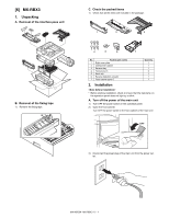
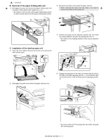
B. Removal of the paper holding plate unit, C. Installation of the interface pass unit
 |
View all Sharp MX-M363N manuals
Add to My Manuals
Save this manual to your list of manuals |
Page 39 highlights
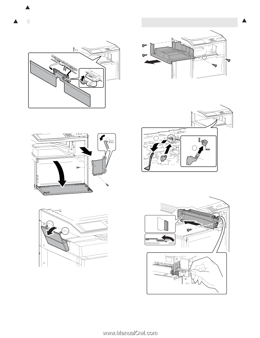
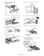
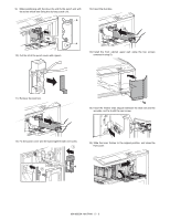
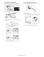
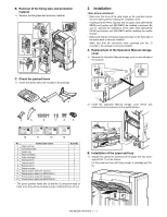
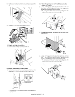
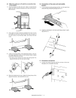
1 : '10/Jun/18 B. Removal of the paper holding plate unit 1 1) Disengage the pawl, and remove the paper holding plate and the paper holding plate holder together as a unit. * Be careful to remove both of the paper holding plate (which is easily removed alone) and the paper holding plate holder. 3) Remove the screws, and remove the paper exit tray. * When removing the paper exit tray, there is no need to 1 remove the screws in the section (A). A 4) Remove the paper exit full detection actuator (A), and install the reverse detection actuator (B) (package part No. 6). * Be careful of the installing direction of the reverse detection actuator. C. Installation of the interface pass unit 1) Open the front cabinet. Remove the screws, and remove the front cabinet upper. 1 A B 2 B 2) Disengage the pawls, and remove the paper exit tray cover. 5) Engage the projection of the main unit frame with the hole in the right cover plate (package part No. 1), and install the right cover plate and fix it with the fixing screw A (package part No. 4). * Be sure to clamp and fix the paper exit tray shifter side plate with the fixing guide. MX-M503N MX-RBX3 6 - 2
-
 1
1 -
2
-
3
-
4
-
5
-
6
-
7
-
8
-
9
-
10
-
11
-
12
-
13
-
14
-
15
-
16
-
17
-
18
-
19
-
20
-
21
-
22
-
23
-
24
-
25
-
26
-
27
-
28
-
29
-
30
-
31
-
32
-
33
-
 34
34 -
 35
35 -
 36
36 -
 37
37 -
 38
38 -
 39
39 -
 40
40 -
 41
41 -
 42
42 -
 43
43 -
 44
44 -
45
-
46
-
47
-
48
-
49
-
50
-
51
-
52
-
53
-
54
-
55
-
56
-
57
-
58
-
59
-
60
-
61
-
62
-
63
-
64
-
65
-
66
-
67
-
68
-
69
-
70
-
71
-
72
-
73
-
74
-
75
-
76
-
77
-
78
-
79
-
80
-
81
-
82
-
83
-
84
-
85
-
86
-
87
-
88
-
89
-
90
-
91
-
92
-
93
-
94
-
95
-
96
-
97
-
98
-
99
-
100
-
101
-
102
-
103
-
104
-
105
-
106
-
107
-
108
-
109
-
110
-
111
-
112
-
113
-
114
-
115
-
116
-
117
 |
 |