Sharp MX-M363N Installation Manual - Page 31
screw package part No. 8., Check to insure that the slide roller is in the rail groove,
 |
View all Sharp MX-M363N manuals
Add to My Manuals
Save this manual to your list of manuals |
Page 31 highlights
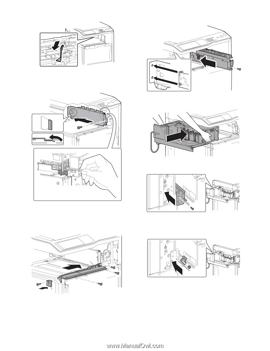
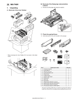
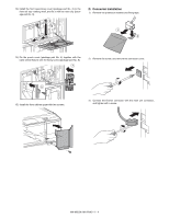
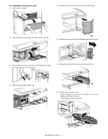
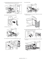
5) Remove the paper exit full detection actuator. 9) Fix the dummy punch unit (package part No. 3) with the fixing screw (package part No. 8). 6) Engage the projection on the main unit frame with the hole in the finisher fixing plate (package part No. 1). 7) Fix the right cover plate with the fixing screw (package part No. 8). 10) Check to insure that the slide roller is in the rail groove, and insert the inner finisher. 11) Fix the rear slide rail with the fixing screw (package part No. 8). * Fix the side plate of the paper exit shifter with the fixing guide. 8) Install the front slide rail (A) (package part No. 2) with the three fixing screws (package part No. 8), and install the left front cover (B) (package part No. 6) with one fixing screw (package part No. 8). 12) After pushing the intermediate rail of accuride, insert the finisher slide stopper (package part No. 7) between the rear slide rail and the accuride. Fix it with the coin screw (package part No. 10). A B MX-M503N MX-FNX9 4 - 3
-
 1
1 -
2
-
3
-
4
-
5
-
6
-
7
-
8
-
9
-
10
-
11
-
12
-
13
-
14
-
15
-
16
-
17
-
18
-
19
-
20
-
21
-
22
-
23
-
24
-
25
-
 26
26 -
 27
27 -
 28
28 -
 29
29 -
 30
30 -
 31
31 -
 32
32 -
 33
33 -
 34
34 -
 35
35 -
 36
36 -
37
-
38
-
39
-
40
-
41
-
42
-
43
-
44
-
45
-
46
-
47
-
48
-
49
-
50
-
51
-
52
-
53
-
54
-
55
-
56
-
57
-
58
-
59
-
60
-
61
-
62
-
63
-
64
-
65
-
66
-
67
-
68
-
69
-
70
-
71
-
72
-
73
-
74
-
75
-
76
-
77
-
78
-
79
-
80
-
81
-
82
-
83
-
84
-
85
-
86
-
87
-
88
-
89
-
90
-
91
-
92
-
93
-
94
-
95
-
96
-
97
-
98
-
99
-
100
-
101
-
102
-
103
-
104
-
105
-
106
-
107
-
108
-
109
-
110
-
111
-
112
-
113
-
114
-
115
-
116
-
117
 |
 |