Sharp MX-M363N Installation Manual - Page 87
D. Reattach the control PWB and the right cabinet rear.
 |
View all Sharp MX-M363N manuals
Add to My Manuals
Save this manual to your list of manuals |
Page 87 highlights
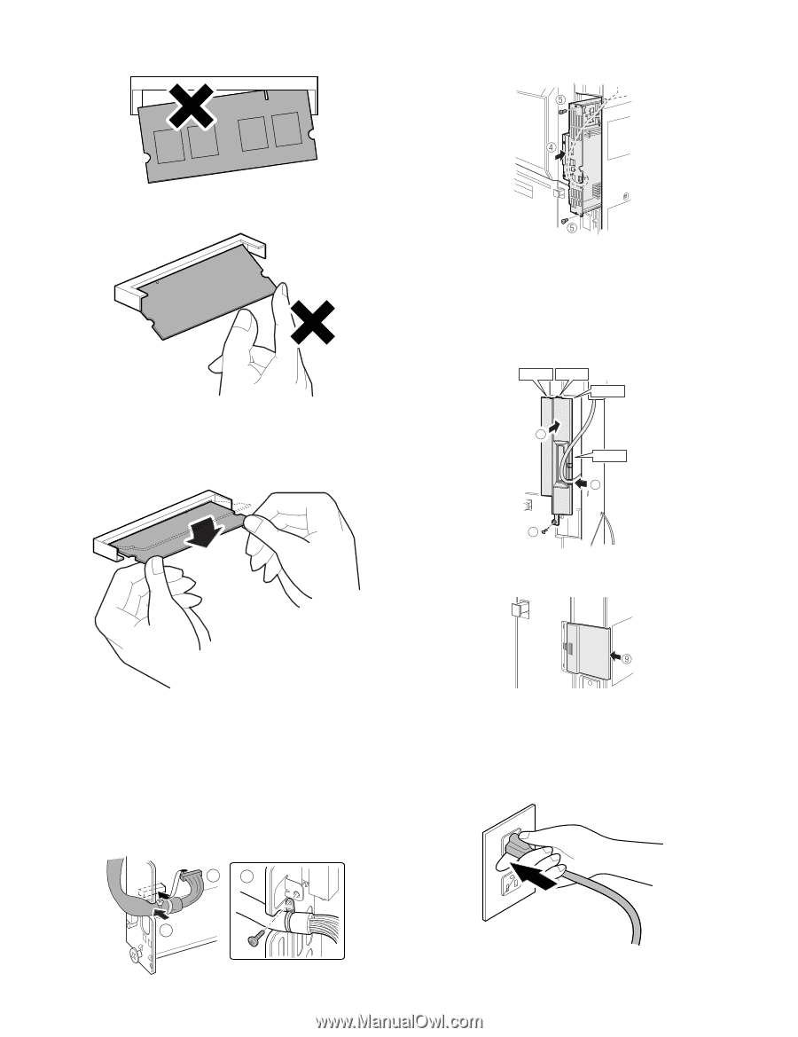
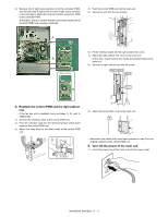
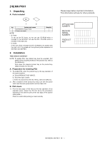
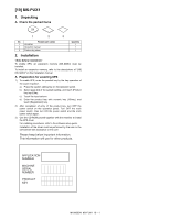
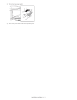
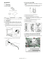
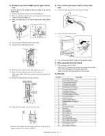
NOTE: Avoid diagonal insertion of the expansion memory board for the slot. 4) Push the control PWB unit into the main unit. 5) Secure the unit with the two screws. NOTE: Do not push one end of the expansion memory board by one hand. b) Hold the both ends of the expansion memory board with both hands, and put down the expansion memory so that it is vertical to the PWB. At that time, check to confirm that the hooks on the left and the right sides of the slot are securely locked. • If the fax box unit is installed, carry out step 6) additionally. 6) Fit the interface cable into the right cabinet rear cover. 7) Attach the right cabinet rear cover to the main unit. At this time, check that the four hooks are properly fitted to the main unit. 8) Secure the right cabinet rear with the screw. Hook 1 Hook 2 Hook 3 7 Hook 4 6 8 9) Attach the ozone filter cover to the main unit. D. Reattach the control PWB and the right cabinet rear. • If the fax box unit is installed, carry out steps 1), 2), and 3) additionally. 1) Connect the interface cable to the control PWB unit. 2) Push the interface cable into the recessed portion of the sheet metal on the control PWB unit. 3) Attach the snap band to the sheet metal of the control PWB unit. 13 • Reconnect the cables that have been removed in step B to the original positions of the control PWB unit. E. Turn on the main power switch of the main unit. 1) Insert the power plug of the main unit to the outlet. 2 MX-M503N MX-SMX3 20 - 2
-
 1
1 -
2
-
3
-
4
-
5
-
6
-
7
-
8
-
9
-
10
-
11
-
12
-
13
-
14
-
15
-
16
-
17
-
18
-
19
-
20
-
21
-
22
-
23
-
24
-
25
-
26
-
27
-
28
-
29
-
30
-
31
-
32
-
33
-
34
-
35
-
36
-
37
-
38
-
39
-
40
-
41
-
42
-
43
-
44
-
45
-
46
-
47
-
48
-
49
-
50
-
51
-
52
-
53
-
54
-
55
-
56
-
57
-
58
-
59
-
60
-
61
-
62
-
63
-
64
-
65
-
66
-
67
-
68
-
69
-
70
-
71
-
72
-
73
-
74
-
75
-
76
-
77
-
78
-
79
-
80
-
81
-
 82
82 -
 83
83 -
 84
84 -
 85
85 -
 86
86 -
 87
87 -
 88
88 -
 89
89 -
 90
90 -
 91
91 -
 92
92 -
93
-
94
-
95
-
96
-
97
-
98
-
99
-
100
-
101
-
102
-
103
-
104
-
105
-
106
-
107
-
108
-
109
-
110
-
111
-
112
-
113
-
114
-
115
-
116
-
117
 |
 |