Sharp MX-M363N Installation Manual - Page 44
E. Connection of the main unit and saddle finisher, F. Connector connection
 |
View all Sharp MX-M363N manuals
Add to My Manuals
Save this manual to your list of manuals |
Page 44 highlights
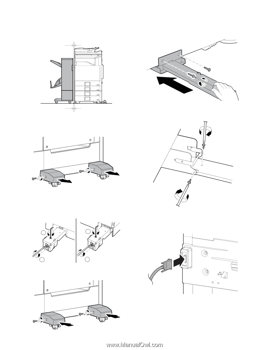
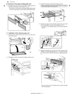
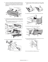
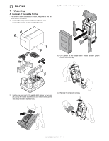
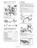
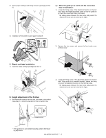
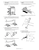
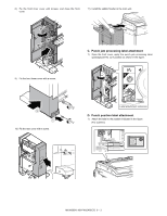
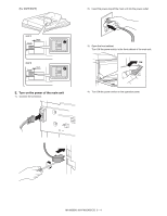
(2) When the guide pin is fit with the connection hole in the finisher: 1) Insert the finisher into the main unit. Check to insure that the upper and lower clearances between the main unit and the finisher are even. Clearance E. Connection of the main unit and saddle finisher 1) Fix the connection plate (package part No. 2) to the paper feed desk with fixing screws B (package part No. 7). Clearance 2) If the upper and lower clearances between the main unit and the finisher are not even, remove the screw (one for each) of the foot covers on the front/rear sides, and remove the foot cover. 2) Install the rail bracket to the frame with fixing screws C (package part No. 8). 3) Loosen four fixing screws of the adjustment section, and turn the height adjustment screws on the front/rear sides to adjust so that the clearances are even. * By making space between the main body and ground, the adjustment screw can be turned by the finger. 2 2 F. Connector connection 1) Connect the finisher connector with the connector of the interface pass unit, and tighten the screw. 1 1 4) When the clearances are even, tighten the fixing screw of the adjustment section, and install the foot cover. MX-M503N MX-FN10 7 - 4
-
 1
1 -
2
-
3
-
4
-
5
-
6
-
7
-
8
-
9
-
10
-
11
-
12
-
13
-
14
-
15
-
16
-
17
-
18
-
19
-
20
-
21
-
22
-
23
-
24
-
25
-
26
-
27
-
28
-
29
-
30
-
31
-
32
-
33
-
34
-
35
-
36
-
37
-
38
-
 39
39 -
 40
40 -
 41
41 -
 42
42 -
 43
43 -
 44
44 -
 45
45 -
 46
46 -
 47
47 -
 48
48 -
 49
49 -
50
-
51
-
52
-
53
-
54
-
55
-
56
-
57
-
58
-
59
-
60
-
61
-
62
-
63
-
64
-
65
-
66
-
67
-
68
-
69
-
70
-
71
-
72
-
73
-
74
-
75
-
76
-
77
-
78
-
79
-
80
-
81
-
82
-
83
-
84
-
85
-
86
-
87
-
88
-
89
-
90
-
91
-
92
-
93
-
94
-
95
-
96
-
97
-
98
-
99
-
100
-
101
-
102
-
103
-
104
-
105
-
106
-
107
-
108
-
109
-
110
-
111
-
112
-
113
-
114
-
115
-
116
-
117
 |
 |