Sharp MX-M363N Installation Manual - Page 54
F. Attaching the cushion, G. Check of the connected position of main unit and finisher, H. Adjustment
 |
View all Sharp MX-M363N manuals
Add to My Manuals
Save this manual to your list of manuals |
Page 54 highlights
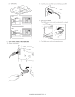
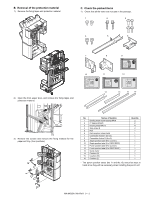
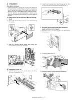
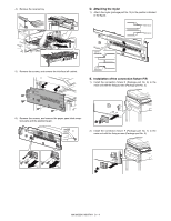
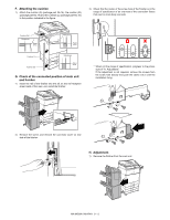
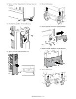
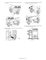
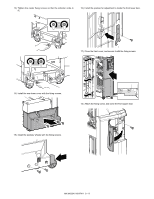
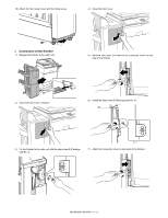
F. Attaching the cushion 1) Attach the cushion (S) (package part No.14), the cushion (M) (package part No.15) and the cushion (L) (package part No.16) to the position indicated in the figure. 3) Check that the center of the screw hole of the finisher is in the range of specification of an oval hole of the connection fixture that exist on main body rear side. Cushion (M) Reference Reference Reference Reference Cushion (L) Cushion (S) Reference Reference G. Check of the connected position of main unit and finisher 1) Insert the rail of the finisher into the slit on the rail reception sheet metal of the main unit, install the finisher. * When not the range of specification, progress to the procedure of "H. Adjustment". If the adjustment is not required, remove the screws from the screw hole directly and push the caster into it until the installation fixing. 2) Remove the screw, and remove the connector cover on rear side of the finisher. H. Adjustment 1) Remove the finisher from the main unit. MX-M503N MX-FN11 9 - 5
-
 1
1 -
2
-
3
-
4
-
5
-
6
-
7
-
8
-
9
-
10
-
11
-
12
-
13
-
14
-
15
-
16
-
17
-
18
-
19
-
20
-
21
-
22
-
23
-
24
-
25
-
26
-
27
-
28
-
29
-
30
-
31
-
32
-
33
-
34
-
35
-
36
-
37
-
38
-
39
-
40
-
41
-
42
-
43
-
44
-
45
-
46
-
47
-
48
-
 49
49 -
 50
50 -
 51
51 -
 52
52 -
 53
53 -
 54
54 -
 55
55 -
 56
56 -
 57
57 -
 58
58 -
 59
59 -
60
-
61
-
62
-
63
-
64
-
65
-
66
-
67
-
68
-
69
-
70
-
71
-
72
-
73
-
74
-
75
-
76
-
77
-
78
-
79
-
80
-
81
-
82
-
83
-
84
-
85
-
86
-
87
-
88
-
89
-
90
-
91
-
92
-
93
-
94
-
95
-
96
-
97
-
98
-
99
-
100
-
101
-
102
-
103
-
104
-
105
-
106
-
107
-
108
-
109
-
110
-
111
-
112
-
113
-
114
-
115
-
116
-
117
 |
 |
