Sharp MX-M363N Installation Manual - Page 91
MX-FR14U/FR14/FR15U/FR15/ FR24U, 1. Unpacking, A. Check the packed items, 2. Installation, A. Turn
 |
View all Sharp MX-M363N manuals
Add to My Manuals
Save this manual to your list of manuals |
Page 91 highlights
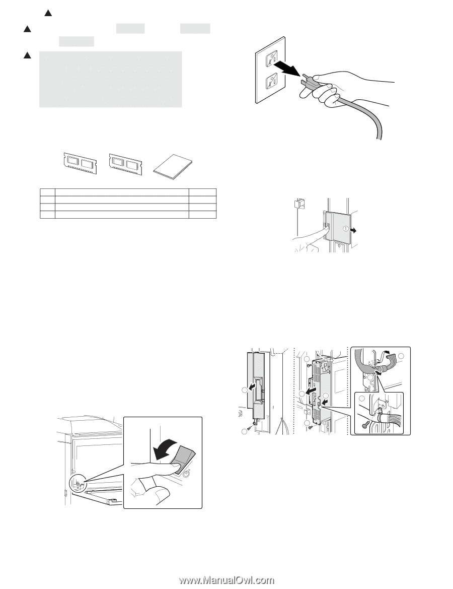
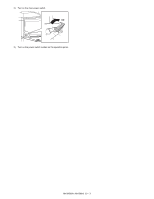
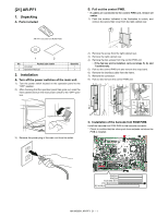
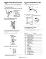
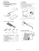
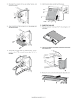
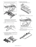
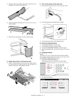
1 : '10/Jun/18 1 [22] MX-FR14U/FR14/FR15U/FR15/ FR24U 1 * MX-FR14U/FR14 For model MX-M283N/M363N/M453N/M503N For model MX-M363U/M453U/M503U with HDD * MX-FR15U/FR15 For model MX-M363U/M453U/M503U without HDD * MX-FR24U For model MX-M282N/M362N/M452N/M502N 1. Unpacking A. Check the packed items 1) Check that all the items are included in the package. MFP_PRG1 MFP_PRG2 1 2 3 No. Packed part names 1 MFP_PRG1 ROM 2 MFP_PRG2 ROM 3 Operation manual Quantity 1 1 1 2. Installation • To enable the data security function, the product key must be acquired. (For the method of acquiring the product key, contact the dealer.) • Before installing the data security kit, be sure to perform backup of data stored in the memory (including HDD) of the main unit. When the data security kit is installed, all the job data stored in the memory (including HDD) of the main unit will be lost. • If the LINE indicator or the DATA indicator for the printer and image transmission on the operation panel is lit or blinking, data that has not been processed remains in the memory of the main unit (including HDD). Output or transmit all the data to clear the data remaining in the main unit and then start installation. (Check to insure that neither the LINE indicator nor the DATA indicator on the operation panel does light up or blink.) A. Turn off the power switches of the main unit. 1) Turn the power switch located on the operation panel to the "OFF" position. 2) After checking that the operation panel has gone out, open the front cabinet and turn the main power switch to the "OFF" position. OFF S3)erRveimcoeve tMhae npouwaelr plug of the main unit from the outlet. B. Pull out the control PWB. • If cables are connected to the control PWB unit, remove all cables. 1) Push the location indicated in the illustration to unlock, and remove the ozone filter cover from the right cabinet rear. 2) Remove the screw from the right cabinet rear. 3) Remove the right cabinet rear. 4) Remove the two screws from the control PWB unit. • If the fax box unit is installed, carry out steps 5), 6), and 7) additionally. 5) Pull out the control PWB unit and remove the snap band. 6) Remove the interface cable from the frame. 7) Remove the connector. 8) Pull out and remove the control PWB unit. 4 7 6 3 8 5 5 4 2 MX-FR14U/FR14/FR15U/FR15/FR24U 22 - 1
-
 1
1 -
2
-
3
-
4
-
5
-
6
-
7
-
8
-
9
-
10
-
11
-
12
-
13
-
14
-
15
-
16
-
17
-
18
-
19
-
20
-
21
-
22
-
23
-
24
-
25
-
26
-
27
-
28
-
29
-
30
-
31
-
32
-
33
-
34
-
35
-
36
-
37
-
38
-
39
-
40
-
41
-
42
-
43
-
44
-
45
-
46
-
47
-
48
-
49
-
50
-
51
-
52
-
53
-
54
-
55
-
56
-
57
-
58
-
59
-
60
-
61
-
62
-
63
-
64
-
65
-
66
-
67
-
68
-
69
-
70
-
71
-
72
-
73
-
74
-
75
-
76
-
77
-
78
-
79
-
80
-
81
-
82
-
83
-
84
-
85
-
 86
86 -
 87
87 -
 88
88 -
 89
89 -
 90
90 -
 91
91 -
 92
92 -
 93
93 -
 94
94 -
 95
95 -
 96
96 -
97
-
98
-
99
-
100
-
101
-
102
-
103
-
104
-
105
-
106
-
107
-
108
-
109
-
110
-
111
-
112
-
113
-
114
-
115
-
116
-
117
 |
 |