Sharp MX-M363N Installation Manual - Page 51
B. Removal of the protection material, C. Check the packed items
 |
View all Sharp MX-M363N manuals
Add to My Manuals
Save this manual to your list of manuals |
Page 51 highlights
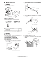
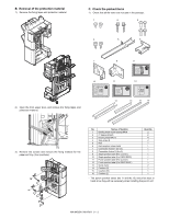
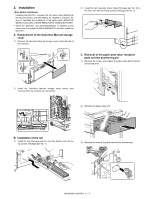
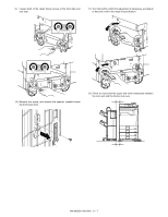
B. Removal of the protection material 1) Remove the fixing tapes and protection material. C. Check the packed items 1) Check that all the items are included in the package. 1 2 3 4 5 6 7 8 9 X3 X3 10 11 12 2) Open the front upper door, and remove the fixing tapes and protection material. 13 14 15 16 3) Remove the screws and remove the fixing material for the paper exit tray. (four positions) No. Names of bundles 1 Binding head round tapping M4x8 2 IT tapping M4x20 3 Binding head M4x12 4 Step screw B 5 Rail 6 Rail reception sheet metal 7 Connection fixture F (for x3) 8 Connection fixture R (for x3) 9 Staple position label (For scanner) 10 Staple position label (For RSPF/DSPF) 11 Punch position label (For scanner) 12 Punch position label (For RSPF/DSPF) 13 Guide mylar 14 Cushion (S) 15 Cushion (M) 16 Cushion (L) Quantity 2 2 4 2 1 1 1 1 1 1 1 1 2 1 1 1 * The punch position labels (No.11 and No.12) should be kept at hand since they will be necessary when installing the punch unit. MX-M503N MX-FN11 9 - 2
-
 1
1 -
2
-
3
-
4
-
5
-
6
-
7
-
8
-
9
-
10
-
11
-
12
-
13
-
14
-
15
-
16
-
17
-
18
-
19
-
20
-
21
-
22
-
23
-
24
-
25
-
26
-
27
-
28
-
29
-
30
-
31
-
32
-
33
-
34
-
35
-
36
-
37
-
38
-
39
-
40
-
41
-
42
-
43
-
44
-
45
-
 46
46 -
 47
47 -
 48
48 -
 49
49 -
 50
50 -
 51
51 -
 52
52 -
 53
53 -
 54
54 -
 55
55 -
 56
56 -
57
-
58
-
59
-
60
-
61
-
62
-
63
-
64
-
65
-
66
-
67
-
68
-
69
-
70
-
71
-
72
-
73
-
74
-
75
-
76
-
77
-
78
-
79
-
80
-
81
-
82
-
83
-
84
-
85
-
86
-
87
-
88
-
89
-
90
-
91
-
92
-
93
-
94
-
95
-
96
-
97
-
98
-
99
-
100
-
101
-
102
-
103
-
104
-
105
-
106
-
107
-
108
-
109
-
110
-
111
-
112
-
113
-
114
-
115
-
116
-
117
 |
 |
