Sharp MX-M363N Installation Manual - Page 68
MX-FXX2, 1. Unpacking, A. Parts included, 2. Installation, A. Turn off the power switches of
 |
View all Sharp MX-M363N manuals
Add to My Manuals
Save this manual to your list of manuals |
Page 68 highlights
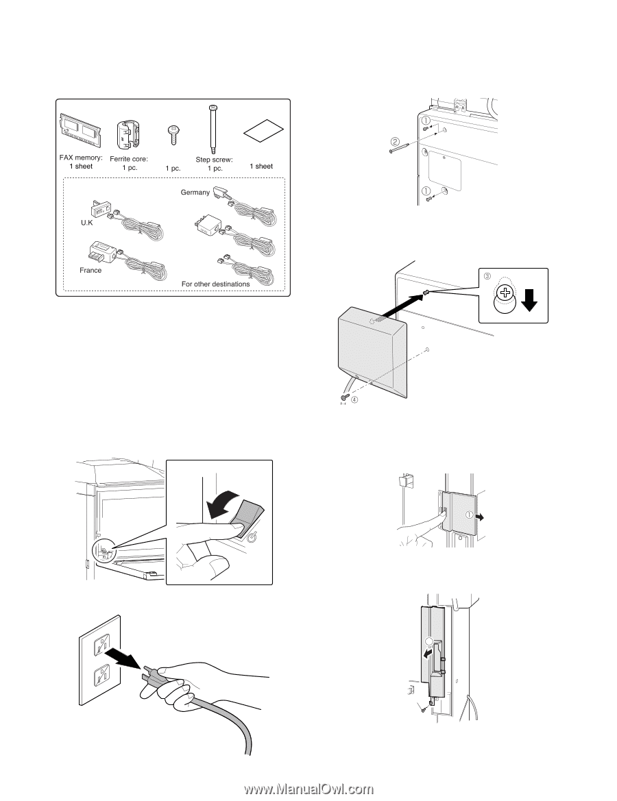
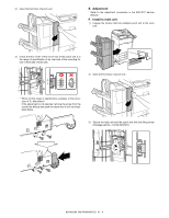
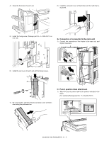
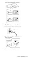
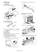
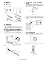
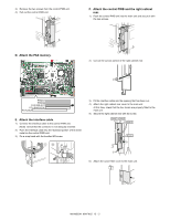
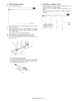
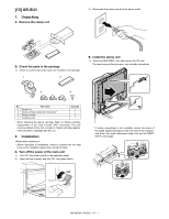
M[1X-2M]50M3NX-FXX2 1. Unpacking A. Parts included SBe. rAvtitacceh Mthaenufaaxlbox unit to the rear part of the main unit. 1) Remove the two screws from the rear cabinet of the main unit. 2) Attach the supplied step screw to one of the two positions from which the screws are removed. Line cable: M3 Screw: Installation directions: Australia 3) Insert the step screw into the mounting hole of the fax box unit. 4) Use a screw that has been removed in step 1) to secure the fax box unit. 2. Installation • Start installation after checking that the LINE indicator and the DATA indicator below it on the operation panel are neither lit nor blinking. A. Turn off the power switches of the main unit. 1) Turn the power switch located on the operation panel to the "OFF" position. 2) After checking that the operation panel has gone out, open the front cabinet and turn the main power switch to the "OFF" opsition. C. Pull out the control PWB. 1) Push the location indicated in the illustration to unlock, and remove the ozone filter cover from the right cabinet rear. OFF 3) Remove the power plug of the main unit from the outlet. 2) Remove the screw from the right cabinet rear and remove the right cabinet rear. 2 Screw MX-M503N MX-FXX2 12 - 1
-
 1
1 -
2
-
3
-
4
-
5
-
6
-
7
-
8
-
9
-
10
-
11
-
12
-
13
-
14
-
15
-
16
-
17
-
18
-
19
-
20
-
21
-
22
-
23
-
24
-
25
-
26
-
27
-
28
-
29
-
30
-
31
-
32
-
33
-
34
-
35
-
36
-
37
-
38
-
39
-
40
-
41
-
42
-
43
-
44
-
45
-
46
-
47
-
48
-
49
-
50
-
51
-
52
-
53
-
54
-
55
-
56
-
57
-
58
-
59
-
60
-
61
-
62
-
 63
63 -
 64
64 -
 65
65 -
 66
66 -
 67
67 -
 68
68 -
 69
69 -
 70
70 -
 71
71 -
 72
72 -
 73
73 -
74
-
75
-
76
-
77
-
78
-
79
-
80
-
81
-
82
-
83
-
84
-
85
-
86
-
87
-
88
-
89
-
90
-
91
-
92
-
93
-
94
-
95
-
96
-
97
-
98
-
99
-
100
-
101
-
102
-
103
-
104
-
105
-
106
-
107
-
108
-
109
-
110
-
111
-
112
-
113
-
114
-
115
-
116
-
117
 |
 |