Sharp MX-M363N Installation Manual - Page 77
C. Pull out the control PWB, D. HDD installation
 |
View all Sharp MX-M363N manuals
Add to My Manuals
Save this manual to your list of manuals |
Page 77 highlights
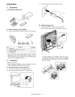
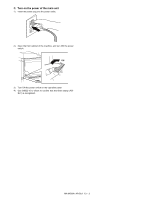
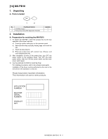
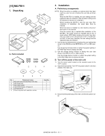
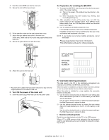
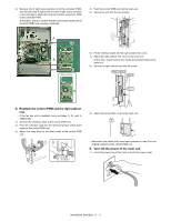
C. Pull out the control PWB • If cables are connected to the control PWB unit, remove all cables. 1) Push the location indicated in the illustration to unlock, and remove the cover from the right cabinet rear. 2) Install the HDD to the MFP PWB frame. When installing the HDD to the MFP PWB frame, attach the anti-vibration rubber to the HDD frame side and fix it with a screw. 2) Remove the screw from the right cabinet rear. 3) Remove the right cabinet rear. 4) Remove the two screws from the control PWB unit. • If the fax box unit is installed, carry out steps 5), 6), and 7) additionally. 5) Pull out the control PWB unit and remove the snap band. 6) Remove the interface cable from the frame. 7) Remove the connector. 8) Pull out and remove the control PWB unit. 4 7 6 3 8 5 5 3) Connect the HDD cable to the HDD. 4) Replace the Flash ROM (Program 1/Program 2) installed to the MFP PWB with the Flash ROM attached to the MX-PB11. 4 2 D. HDD installation 1) Put the cushion material used for packing the MX-PB11 beneath the MFP PWB frame. NOTE: Be sure to perform this procedure in order to protect the memory and the Flash ROM on the MFP PWB. If this procedure is neglected, a stress may be applied to the memory and the Flash ROM on the MFP PWB, causing a trouble. E. Reattach the control PWB and the right cabinet rear • If the fax box unit is installed, carry out steps 1), 2), and 3) additionally. 1) Connect the interface cable to the control PWB unit. 2) Push the interface cable into the recessed portion of the sheet metal on the control PWB unit. 3) Attach the snap band to the sheet metal of the control PWB unit. 13 2 MX-M503N MX-PB11 15 - 2
-
 1
1 -
2
-
3
-
4
-
5
-
6
-
7
-
8
-
9
-
10
-
11
-
12
-
13
-
14
-
15
-
16
-
17
-
18
-
19
-
20
-
21
-
22
-
23
-
24
-
25
-
26
-
27
-
28
-
29
-
30
-
31
-
32
-
33
-
34
-
35
-
36
-
37
-
38
-
39
-
40
-
41
-
42
-
43
-
44
-
45
-
46
-
47
-
48
-
49
-
50
-
51
-
52
-
53
-
54
-
55
-
56
-
57
-
58
-
59
-
60
-
61
-
62
-
63
-
64
-
65
-
66
-
67
-
68
-
69
-
70
-
71
-
 72
72 -
 73
73 -
 74
74 -
 75
75 -
 76
76 -
 77
77 -
 78
78 -
 79
79 -
 80
80 -
 81
81 -
 82
82 -
83
-
84
-
85
-
86
-
87
-
88
-
89
-
90
-
91
-
92
-
93
-
94
-
95
-
96
-
97
-
98
-
99
-
100
-
101
-
102
-
103
-
104
-
105
-
106
-
107
-
108
-
109
-
110
-
111
-
112
-
113
-
114
-
115
-
116
-
117
 |
 |
