Sharp MX-M363N Installation Manual - Page 90
D. Reattach the control PWB and the right cabinet rear., E. Turn on the main power switch of the main unit., F. PCL expansion font list check, G. Font list
 |
View all Sharp MX-M363N manuals
Add to My Manuals
Save this manual to your list of manuals |
Page 90 highlights
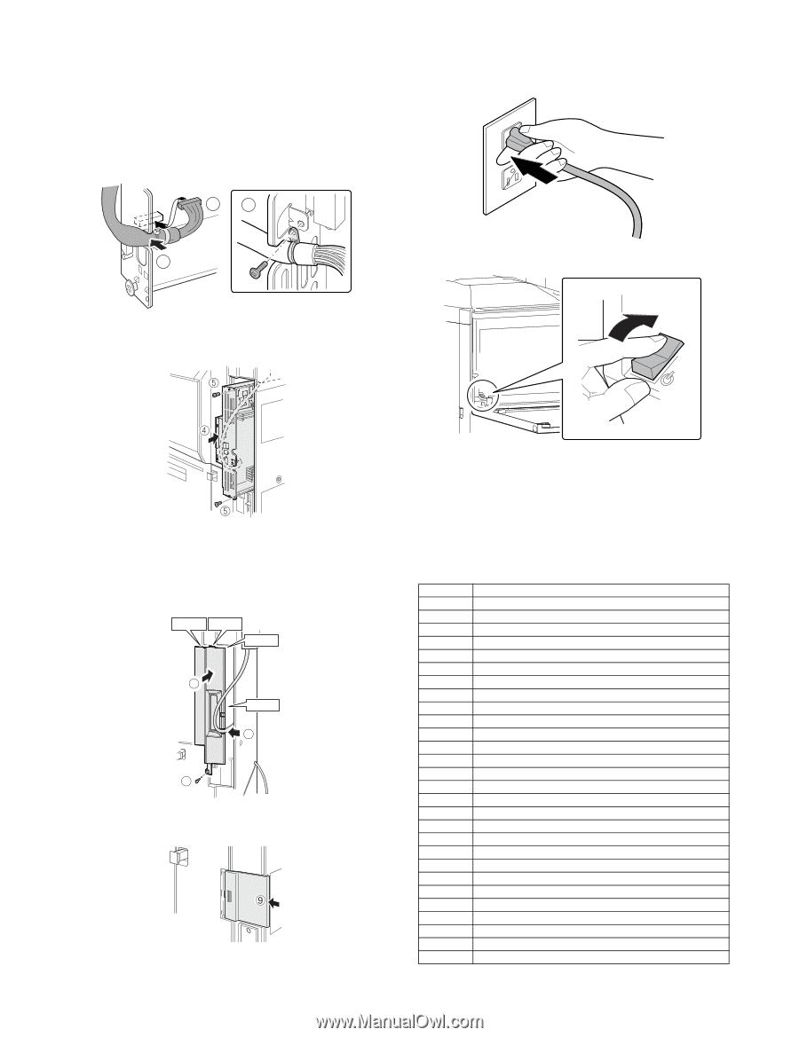
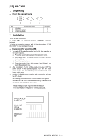
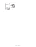
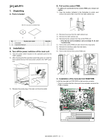
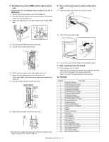
D. Reattach the control PWB and the right cabinet rear. • If the fax box unit is installed, carry out steps 1), 2), and 3) additionally. 1) Connect the interface cable to the control PWB unit. 2) Push the interface cable into the recessed portion of the sheet metal on the control PWB unit. 3) Attach the snap band to the sheet metal of the control PWB unit. 13 E. Turn on the main power switch of the main unit. 1) Insert the power plug of the main unit to the outlet. 2 2) Turn on the main power switch. ON 4) Push the control PWB unit into the main unit. 5) Secure the unit with the two screws. 6) Fit the interface cable into the right cabinet rear cover. 7) Attach the right cabinet rear cover to the main unit. At this time, check that the four hooks are properly fitted to the main unit. 8) Secure the right cabinet rear with the screw. Hook 1 Hook 2 Hook 3 7 Hook 4 6 8 9) Attach the ozone filter cover to the main unit. • Reconnect the cables that have been removed in step B to the original positions of the control PWB unit. 3) Turn on the power switch located on the operation panel. F. PCL expansion font list check 1) PCL expansion font list check Select the PCL expansion font list by the procedures described in the printer test page in the system setup guide. Check to confirm that the barcode font list is printed. G. Font list Font No. 1 2 3 4 5 6 7 8 9 10 11 12 13 14 15 16 17 18 19 20 21 22 23 24 25 26 27 28 Font name Code128TT-Regular Code128-NarrowTT-Regular Code128-WideTT-Regular Code39HalfInch-Regular Code39OneInch-Regular Code39QuarterInch-Regular Code39SmallHigh-Regular Code39Slim-Regular Code39SmallLow-Regular Code39SmallMedium-Regular Code39Wide-Regular Codabar-Regular Interleaved2of5-Regular Interleaved2of5-Thin-Regular OCR-A OCR-B OCR-B-C39-Regular UPC-Half UPC-Half-Bars UPC-HalfMusic UPC-HalfNarrow UPC-HalfThin UPC-Tall-Regular UPC-TallBarsThin-regular UPC-TallMusicThin-Regular UPC-TallNarrow-Regular UPC-TallThin-regular ZipCodeBarcode-Regular MX-M503N AR-PF1 21 - 2
-
 1
1 -
2
-
3
-
4
-
5
-
6
-
7
-
8
-
9
-
10
-
11
-
12
-
13
-
14
-
15
-
16
-
17
-
18
-
19
-
20
-
21
-
22
-
23
-
24
-
25
-
26
-
27
-
28
-
29
-
30
-
31
-
32
-
33
-
34
-
35
-
36
-
37
-
38
-
39
-
40
-
41
-
42
-
43
-
44
-
45
-
46
-
47
-
48
-
49
-
50
-
51
-
52
-
53
-
54
-
55
-
56
-
57
-
58
-
59
-
60
-
61
-
62
-
63
-
64
-
65
-
66
-
67
-
68
-
69
-
70
-
71
-
72
-
73
-
74
-
75
-
76
-
77
-
78
-
79
-
80
-
81
-
82
-
83
-
84
-
 85
85 -
 86
86 -
 87
87 -
 88
88 -
 89
89 -
 90
90 -
 91
91 -
 92
92 -
 93
93 -
 94
94 -
 95
95 -
96
-
97
-
98
-
99
-
100
-
101
-
102
-
103
-
104
-
105
-
106
-
107
-
108
-
109
-
110
-
111
-
112
-
113
-
114
-
115
-
116
-
117
 |
 |