Sharp MX-M363N Installation Manual - Page 34
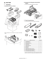
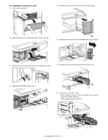
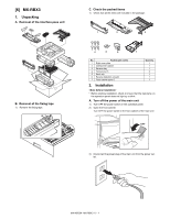
MX-PNX1, 1. Unpacking, A. Removal of the punch unit, B. Removal of the fixing tape, C. Check
 |
View all Sharp MX-M363N manuals
Add to My Manuals
Save this manual to your list of manuals |
Page 34 highlights
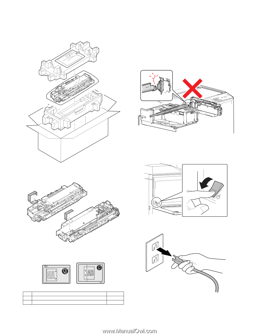
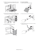
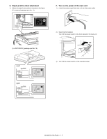
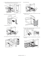
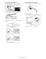
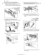
M[5X-]M50M3NX-PNX1 1. Unpacking A. Removal of the punch unit S2e. rvIincsetaMlalantuioaln * When the punch unit is installed together with installation of the MX-FNX9 (inner finisher), first install the inner finisher, and then install the punch unit. * Before starting installation, check to insure that the data lamp on the operation panel does not light up or blink. * Do not install the punch unit first because doing so would cause interference between the inner finisher slide rail and the punch unit drawer connector (possibly resulting in failure) when you attempt to install the inner finisher. B. Removal of the fixing tape 1) Remove the fixing tape. A. Turn off the power of the main unit 1) Turn OFF the power switch on the operation panel. 2) Open the front cabinet. Turn OFF the power switch in the front cabinet of the main unit. OFF C. Check the packed items 1) Check that all the items are included in the package. 3) Disconnect the power plug of the main unit from the power outlet. 1 2 No. Packed part names 1 Punch position label (For scanner) 2 Punch position label (For RSPF/DSPF) Quantity 1 1 * Do not use the punch position label which is one of the packed parts, but use one packed in the package of the finisher (MXFNX9). MX-M503N MX-PNX1 5 - 1
-
 1
1 -
2
-
3
-
4
-
5
-
6
-
7
-
8
-
9
-
10
-
11
-
12
-
13
-
14
-
15
-
16
-
17
-
18
-
19
-
20
-
21
-
22
-
23
-
24
-
25
-
26
-
27
-
28
-
 29
29 -
 30
30 -
 31
31 -
 32
32 -
 33
33 -
 34
34 -
 35
35 -
 36
36 -
 37
37 -
 38
38 -
 39
39 -
40
-
41
-
42
-
43
-
44
-
45
-
46
-
47
-
48
-
49
-
50
-
51
-
52
-
53
-
54
-
55
-
56
-
57
-
58
-
59
-
60
-
61
-
62
-
63
-
64
-
65
-
66
-
67
-
68
-
69
-
70
-
71
-
72
-
73
-
74
-
75
-
76
-
77
-
78
-
79
-
80
-
81
-
82
-
83
-
84
-
85
-
86
-
87
-
88
-
89
-
90
-
91
-
92
-
93
-
94
-
95
-
96
-
97
-
98
-
99
-
100
-
101
-
102
-
103
-
104
-
105
-
106
-
107
-
108
-
109
-
110
-
111
-
112
-
113
-
114
-
115
-
116
-
117
 |
 |