Sharp MX-M363N Installation Manual - Page 28
R side, When the shift is in the front side
 |
View all Sharp MX-M363N manuals
Add to My Manuals
Save this manual to your list of manuals |
Page 28 highlights
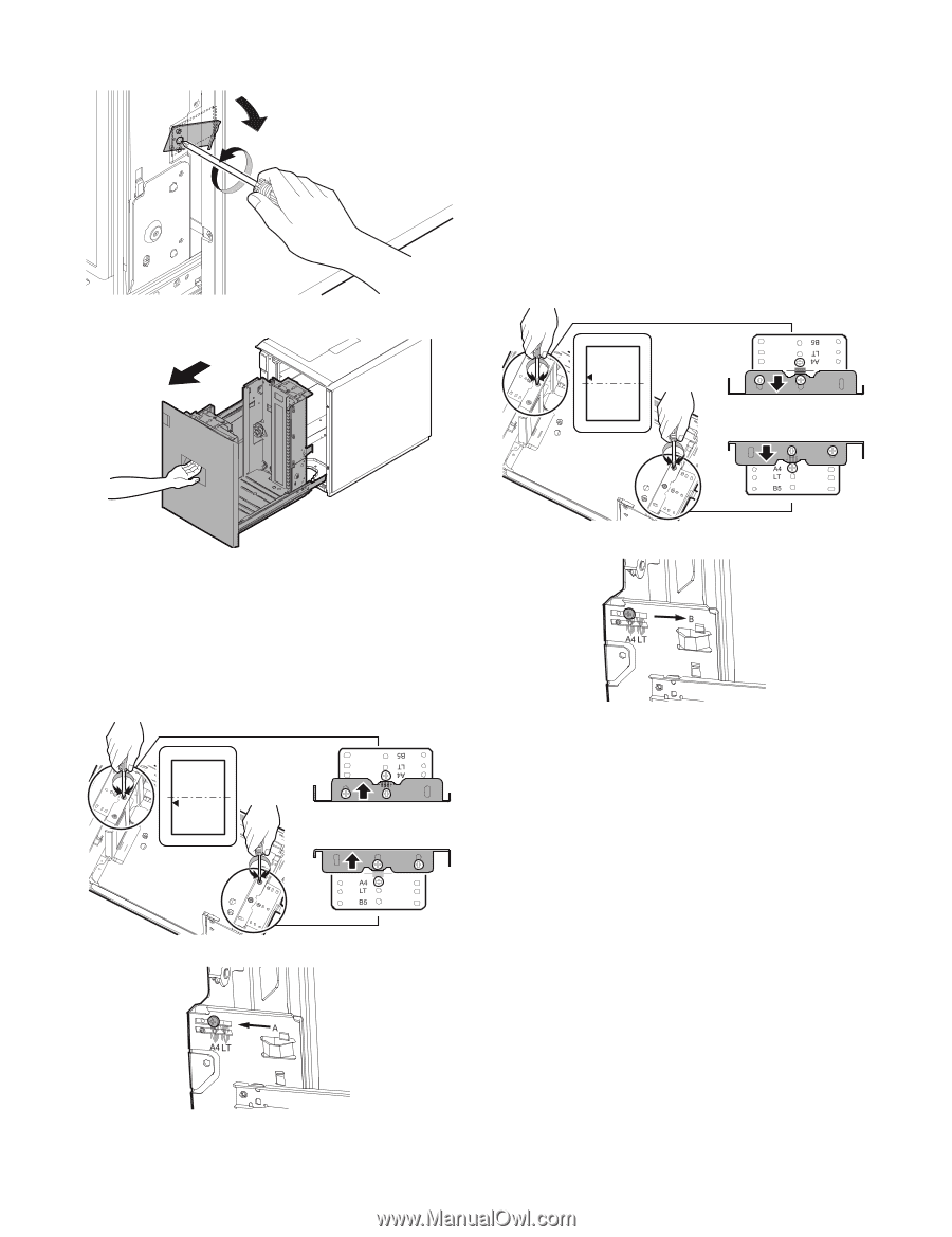
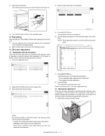
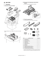
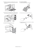
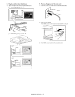
2) Loosen the stopper fixing screw (1 pc) on the right lower side of the tray so that the stopper does not function. 3) Pull out the tray again until it stops. 2) Slowly insert the tray to the original position. Then make a copy to check to insure that there is no more shift. Repeat the procedures until there is no shift. b. When the shift is in the rear side To adjust the print line in the direction B from the paper center as shown in the figure: 1) Loosen two fixing screws (red screws) of the front/rear size guide adjustment plate, and move the size guide adjustment plate in the direction B (F side) by the shift amount, and tighten the red fixing screws (2 for each). Restore the stopper to the original position, and fix it with the fixing screws. Move the auxiliary guide in the direction B by the same size. Check to insure that the stopper pawl is engaged with the stopper reception of the large capacity tray. R side B a. When the shift is in the front side To adjust the print line in the direction A from the paper center as shown in the figure: 1) Loosen two fixing screws (red screws) of the front/rear size guide adjustment plate, and move the size guide adjustment plate in the direction A (R side) by the shift amount, and tighten the red fixing screws (2 for each). Move the auxiliary guide in the direction A by the same size. R side F side 2) Slowly insert the tray to the original position. Then make a copy to check to insure that there is no more shift. Repeat the procedures until there is no shift. A F side Slightly push the tray, restore the stopper to the original position, and fix the fixing screw. Check to insure that the stopper pawl is engaged with the stopper reception of the large capacity tray. MX-M503N MX-LCX1 3 - 9
-
 1
1 -
2
-
3
-
4
-
5
-
6
-
7
-
8
-
9
-
10
-
11
-
12
-
13
-
14
-
15
-
16
-
17
-
18
-
19
-
20
-
21
-
22
-
 23
23 -
 24
24 -
 25
25 -
 26
26 -
 27
27 -
 28
28 -
 29
29 -
 30
30 -
 31
31 -
 32
32 -
 33
33 -
34
-
35
-
36
-
37
-
38
-
39
-
40
-
41
-
42
-
43
-
44
-
45
-
46
-
47
-
48
-
49
-
50
-
51
-
52
-
53
-
54
-
55
-
56
-
57
-
58
-
59
-
60
-
61
-
62
-
63
-
64
-
65
-
66
-
67
-
68
-
69
-
70
-
71
-
72
-
73
-
74
-
75
-
76
-
77
-
78
-
79
-
80
-
81
-
82
-
83
-
84
-
85
-
86
-
87
-
88
-
89
-
90
-
91
-
92
-
93
-
94
-
95
-
96
-
97
-
98
-
99
-
100
-
101
-
102
-
103
-
104
-
105
-
106
-
107
-
108
-
109
-
110
-
111
-
112
-
113
-
114
-
115
-
116
-
117
 |
 |