Sharp MX-M363N Installation Manual - Page 92
C. Mount the data security kit ROMs to the control PWB unit.
 |
View all Sharp MX-M363N manuals
Add to My Manuals
Save this manual to your list of manuals |
Page 92 highlights
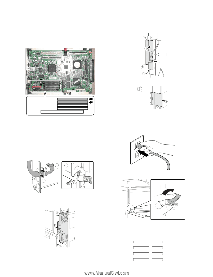
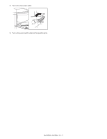
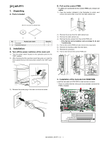
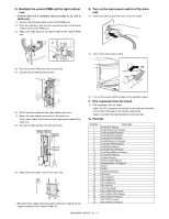
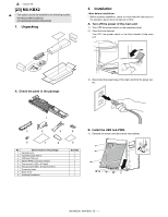
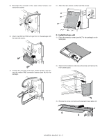
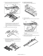
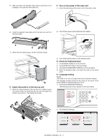
C. Mount the data security kit ROMs to the control PWB unit. Remove the ROMs (PROG1 and PROG2) from the control PWB and replace them with the data security kit ROMs (MFP_PRG1 and MFP_PRG2). When mounting the data security kit ROMs, insert them to the same positions in the same orientations as those before replacement until they click and ensure that the inserted ROMs are locked with the sockets. 6) Fit the interface cable into the right cabinet rear cover. 7) Attach the right cabinet rear cover to the main unit. At this time, check that the four hooks are properly fitted to the main unit. 8) Secure the right cabinet rear with the screw. Hook 1 Hook 2 Hook 3 7 Hook 4 6 8 9) Attach the ozone filter cover to the main unit. PROG1 PROG2 FAX IMG EXT PCL/BARCODE PS KANJI D. Reattach the control PWB and the right cabinet rear. • If the fax box unit is installed, carry out steps 1), 2), and 3) additionally. 1) Connect the interface cable to the control PWB unit. 2) Push the interface cable into the recessed portion of the sheet metal on the control PWB unit. 3) Attach the snap band to the sheet metal of the control PWB unit. 13 2 4) Push the control PWB unit into the main unit. 5) Secure the unit with the two screws. • Reconnect the cables that have been removed in step B to the original positions of the control PWB unit. E. Turn on the main power switch of the main unit. 1) Insert the power plug of the main unit to the outlet. 2) Turn on the main power switch. ON • If the fax box unit is installed, carry out step 6) additionally. 3) Turn on the power switch located on the operation panel. 4) Enter the product key of the DSK. Serial Number xxxxxxxxxx PS3 Expansion Kit: [Enable] Internet Fax Expansion Kit: [Enable] Register Register E-mail Alert and Status: [Enable] Register Data Security Kit: [Enable] Register MX-FR14U/FR14/FR15U/FR15/FR24U 22 - 2
-
 1
1 -
2
-
3
-
4
-
5
-
6
-
7
-
8
-
9
-
10
-
11
-
12
-
13
-
14
-
15
-
16
-
17
-
18
-
19
-
20
-
21
-
22
-
23
-
24
-
25
-
26
-
27
-
28
-
29
-
30
-
31
-
32
-
33
-
34
-
35
-
36
-
37
-
38
-
39
-
40
-
41
-
42
-
43
-
44
-
45
-
46
-
47
-
48
-
49
-
50
-
51
-
52
-
53
-
54
-
55
-
56
-
57
-
58
-
59
-
60
-
61
-
62
-
63
-
64
-
65
-
66
-
67
-
68
-
69
-
70
-
71
-
72
-
73
-
74
-
75
-
76
-
77
-
78
-
79
-
80
-
81
-
82
-
83
-
84
-
85
-
86
-
 87
87 -
 88
88 -
 89
89 -
 90
90 -
 91
91 -
 92
92 -
 93
93 -
 94
94 -
 95
95 -
 96
96 -
 97
97 -
98
-
99
-
100
-
101
-
102
-
103
-
104
-
105
-
106
-
107
-
108
-
109
-
110
-
111
-
112
-
113
-
114
-
115
-
116
-
117
 |
 |