Sharp MX-M363N Installation Manual - Page 18
D. Release the lock, E. Connector connection
 |
View all Sharp MX-M363N manuals
Add to My Manuals
Save this manual to your list of manuals |
Page 18 highlights
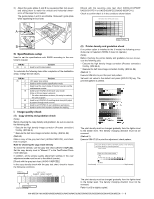
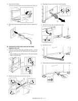
D. Release the lock 1) Pull out each tray. E. Connector connection 1) Remove the screw from the back of the main unit. Remove the connector cover. 2) Turn and remove the fixing material, and remove the caution sheet. 2) Connect the connector. 3) Attach the removed fixing material to the position shown in the figure for storage. 3) Split the removed connector cover along the perforated line. NOTE: Before turning on the power, check to insure that the fixing material of the tray is disengaged. If the power is turned on without disengaging the fixing material, a trouble may be resulted. 4) Close the cassette which was pulled out. 4) Install the connector cover and fix it with a screw. MX-M503N MX-DEX8/DEX9 2 - 4
-
 1
1 -
2
-
3
-
4
-
5
-
6
-
7
-
8
-
9
-
10
-
11
-
12
-
 13
13 -
 14
14 -
 15
15 -
 16
16 -
 17
17 -
 18
18 -
 19
19 -
 20
20 -
 21
21 -
 22
22 -
 23
23 -
24
-
25
-
26
-
27
-
28
-
29
-
30
-
31
-
32
-
33
-
34
-
35
-
36
-
37
-
38
-
39
-
40
-
41
-
42
-
43
-
44
-
45
-
46
-
47
-
48
-
49
-
50
-
51
-
52
-
53
-
54
-
55
-
56
-
57
-
58
-
59
-
60
-
61
-
62
-
63
-
64
-
65
-
66
-
67
-
68
-
69
-
70
-
71
-
72
-
73
-
74
-
75
-
76
-
77
-
78
-
79
-
80
-
81
-
82
-
83
-
84
-
85
-
86
-
87
-
88
-
89
-
90
-
91
-
92
-
93
-
94
-
95
-
96
-
97
-
98
-
99
-
100
-
101
-
102
-
103
-
104
-
105
-
106
-
107
-
108
-
109
-
110
-
111
-
112
-
113
-
114
-
115
-
116
-
117
 |
 |
MX-M503N
MX-DEX8/DEX9
2 – 4
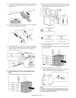
D.
Release the lock
1)
Pull out each tray.
2)
Turn and remove the fixing material, and remove the caution
sheet.
3)
Attach the removed fixing material to the position shown in the
figure for storage.
4)
Close the cassette which was pulled out.
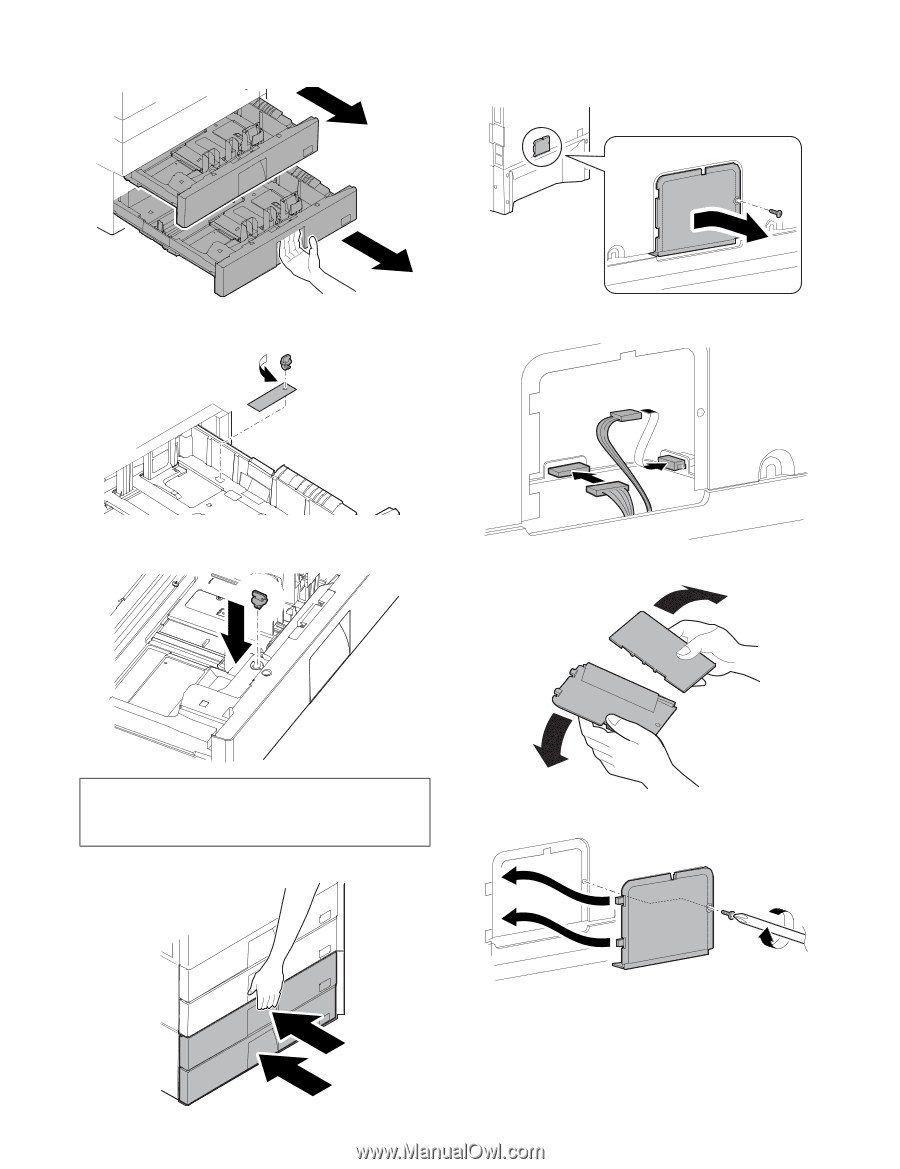
E.
Connector connection
1)
Remove the screw from the back of the main unit. Remove the
connector cover.
2)
Connect the connector.
3)
Split the removed connector cover along the perforated line.
4)
Install the connector cover and fix it with a screw.
NOTE:
Before turning on the power, check to insure that the fixing
material of the tray is disengaged. If the power is turned on
without disengaging the fixing material, a trouble may be
resulted.