Sharp MX-M363N Installation Manual - Page 112
D. RSPF skew adjustment (Front surface mode), Check Method 2]
 |
View all Sharp MX-M363N manuals
Add to My Manuals
Save this manual to your list of manuals |
Page 112 highlights
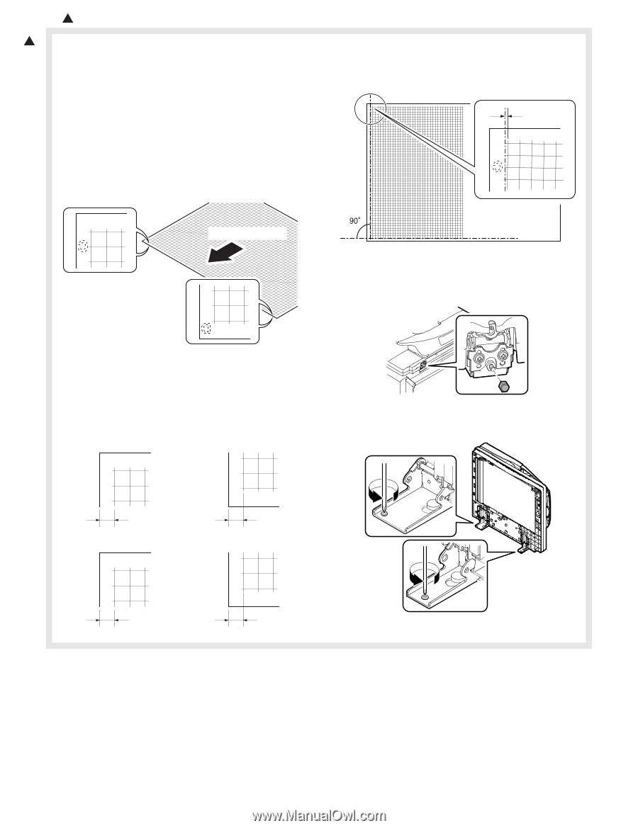
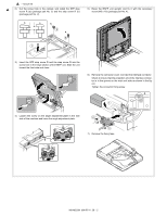
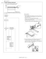
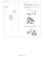
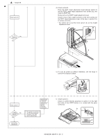
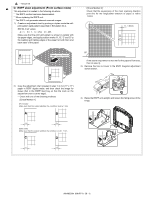
1 : '10/Jun/18 D. RSPF skew adjustment (Front surface mode) 1 This adjustment is needed in the following situations: * The RSPF section has been disassembled. * When replacing the RSPF unit. * The RSPF unit generates skewed scanned images. 1) Create an adjustment chart by printing in duplex mode the selfprint pattern (grid pattern) specified in Simulation 64-2. SIM 64-2 set values A = 1, B = 1, C = 254, D = 255 Make sure that the print grid pattern is almost in parallel with the paper edges, and apply position marks 'A', 'B', 'C' and 'D' to the leading and trailing edges of the paper for both front and back sides of the paper. [Check Method 2] Check that the squareness of the main scanning direction print line for the longitudinal direction of paper is within 1.0mm. 0 - 1.0mm A A Paper pass direction If the above requirement is not met for the paper's front side, then do step 3). 3) Remove the hex nut cover in the RSPF diagonal adjustment screw section. B 2) Copy the adjustment chart (created in step 1) to A3 (11" x 17") paper in RSPF duplex mode, and then check the image for skews (Set in the RSPF feed tray so that the mark on the adjustment chart is at the edge). • Check with one of the following methods. [Check Method 1] (Front side) Make sure that the output satisfies the condition: |a-b| ± 1 mm A B 4) Raise the RSPF unit upright, and loosen the fixing screw of the hinge. a b (Back side) Make sure that the output satisfies the condition: |c-d| ± 1 mm C D c d MX-M503N MX-RP11 28 - 6
-
 1
1 -
2
-
3
-
4
-
5
-
6
-
7
-
8
-
9
-
10
-
11
-
12
-
13
-
14
-
15
-
16
-
17
-
18
-
19
-
20
-
21
-
22
-
23
-
24
-
25
-
26
-
27
-
28
-
29
-
30
-
31
-
32
-
33
-
34
-
35
-
36
-
37
-
38
-
39
-
40
-
41
-
42
-
43
-
44
-
45
-
46
-
47
-
48
-
49
-
50
-
51
-
52
-
53
-
54
-
55
-
56
-
57
-
58
-
59
-
60
-
61
-
62
-
63
-
64
-
65
-
66
-
67
-
68
-
69
-
70
-
71
-
72
-
73
-
74
-
75
-
76
-
77
-
78
-
79
-
80
-
81
-
82
-
83
-
84
-
85
-
86
-
87
-
88
-
89
-
90
-
91
-
92
-
93
-
94
-
95
-
96
-
97
-
98
-
99
-
100
-
101
-
102
-
103
-
104
-
105
-
106
-
 107
107 -
 108
108 -
 109
109 -
 110
110 -
 111
111 -
 112
112 -
 113
113 -
 114
114 -
 115
115 -
 116
116 -
 117
117
 |
 |