Sharp MX-M363N Installation Manual - Page 61
C. Check the packed items, 2. Installation, A. Installation of punch unit
 |
View all Sharp MX-M363N manuals
Add to My Manuals
Save this manual to your list of manuals |
Page 61 highlights
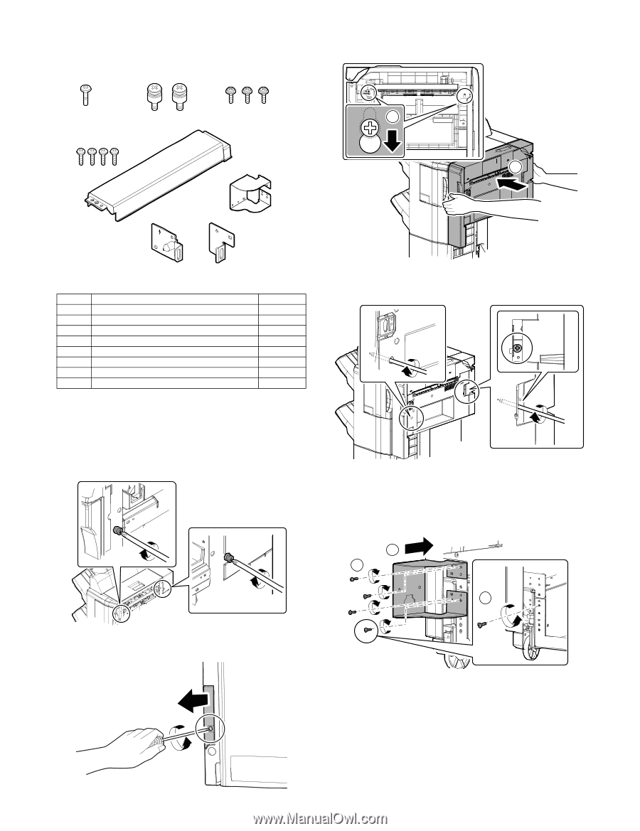
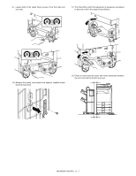
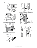
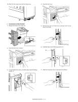
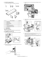
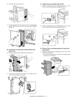
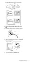
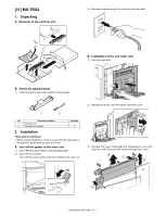
C. Check the packed items 1) Check that all the items are included in the package. 1 2 3 4 5 6 3) Hang the punch unit on the step screws installed to the finisher. 2 1 7 8 P P No. Names of bundles 1 P tight M4x12 2 Step screw A 3 Cap screw M3x6 4 Binding head M4x12 5 Front cover 6 Front cover mounting fixture 7 Connection fixture F (for punch) 8 Connection fixture R (for punch) Quantity 1 2 3 4 1 1 1 1 2. Installation * Before installing the MX-PNX6A/B/C/D, unpack the MX-FN11. A. Installation of punch unit 1) Attach the step screw A (Package part No. 2) to the finisher. 4) Tighten the step screws bundled to the punch unit, fix the punch unit. 5) Attach the front cover mounting fixture (Package part No. 6) with the fixing screws (Package part No. 3). Remove the screw of the finisher, and reuse it. Install it using the reuse screw, and three fixing screws (Package part No. 3) bundled to punch unit. 2 3 1 2) Remove the fixing screw, and remove the connector cover on rear side of the finisher. MX-M503N MX-PNX6A/B/C/D 10 - 2
-
 1
1 -
2
-
3
-
4
-
5
-
6
-
7
-
8
-
9
-
10
-
11
-
12
-
13
-
14
-
15
-
16
-
17
-
18
-
19
-
20
-
21
-
22
-
23
-
24
-
25
-
26
-
27
-
28
-
29
-
30
-
31
-
32
-
33
-
34
-
35
-
36
-
37
-
38
-
39
-
40
-
41
-
42
-
43
-
44
-
45
-
46
-
47
-
48
-
49
-
50
-
51
-
52
-
53
-
54
-
55
-
 56
56 -
 57
57 -
 58
58 -
 59
59 -
 60
60 -
 61
61 -
 62
62 -
 63
63 -
 64
64 -
 65
65 -
 66
66 -
67
-
68
-
69
-
70
-
71
-
72
-
73
-
74
-
75
-
76
-
77
-
78
-
79
-
80
-
81
-
82
-
83
-
84
-
85
-
86
-
87
-
88
-
89
-
90
-
91
-
92
-
93
-
94
-
95
-
96
-
97
-
98
-
99
-
100
-
101
-
102
-
103
-
104
-
105
-
106
-
107
-
108
-
109
-
110
-
111
-
112
-
113
-
114
-
115
-
116
-
117
 |
 |