Sharp MX-M363N Installation Manual - Page 64
G. Connection of connector to the main unit, H. Punch position label attachment
 |
View all Sharp MX-M363N manuals
Add to My Manuals
Save this manual to your list of manuals |
Page 64 highlights
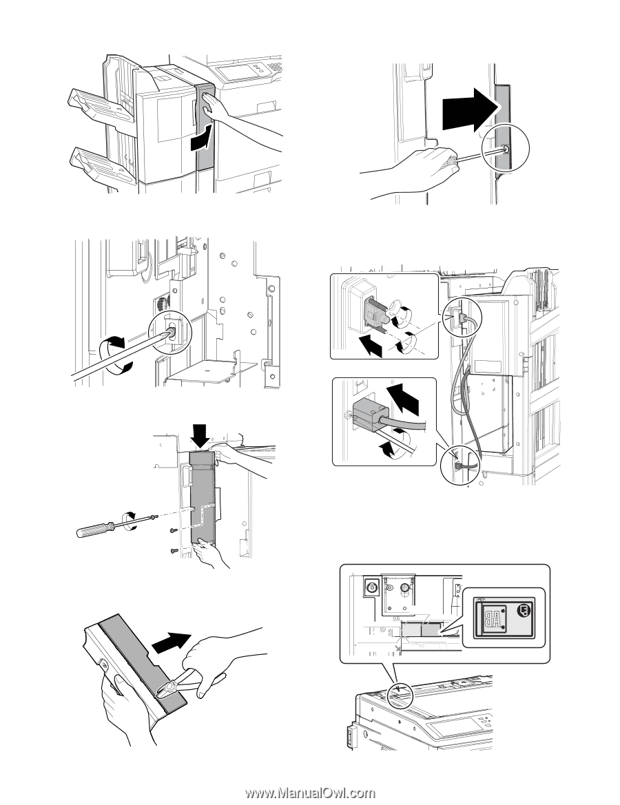
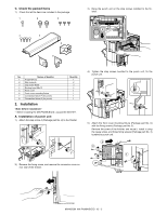
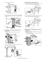
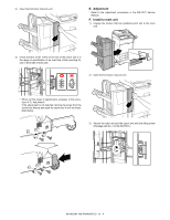
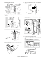
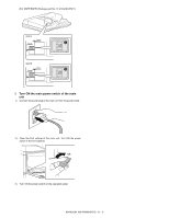
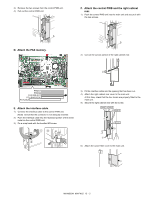
4) Close the front door of punch unit. 8) Install the connector cover of the finisher and fix it with the fixing screw. 5) Install the fixing screw (Package part No. 4 of MX-FN11) on rear side. G. Connection of connector to the main unit 1) Connect two connectors of the finisher to the main unit, and tighten the screws. 6) Install the rear cover of punch unit with the fixing screws. H. Punch position label attachment 1) Attach the punch position label to the position indicated in the figure. [For scanner] (Package part No. 11 of the MX-FN11) 7) By using nippers, split the removed connector cover of the finisher along the perforated line. Corner R end fitting Lose the clearance. First label Second label Label attachment reference Corner of the "upper cabinet rear" Corner R end fitting MX-M503N MX-PNX6A/B/C/D 10 - 5
-
 1
1 -
2
-
3
-
4
-
5
-
6
-
7
-
8
-
9
-
10
-
11
-
12
-
13
-
14
-
15
-
16
-
17
-
18
-
19
-
20
-
21
-
22
-
23
-
24
-
25
-
26
-
27
-
28
-
29
-
30
-
31
-
32
-
33
-
34
-
35
-
36
-
37
-
38
-
39
-
40
-
41
-
42
-
43
-
44
-
45
-
46
-
47
-
48
-
49
-
50
-
51
-
52
-
53
-
54
-
55
-
56
-
57
-
58
-
 59
59 -
 60
60 -
 61
61 -
 62
62 -
 63
63 -
 64
64 -
 65
65 -
 66
66 -
 67
67 -
 68
68 -
 69
69 -
70
-
71
-
72
-
73
-
74
-
75
-
76
-
77
-
78
-
79
-
80
-
81
-
82
-
83
-
84
-
85
-
86
-
87
-
88
-
89
-
90
-
91
-
92
-
93
-
94
-
95
-
96
-
97
-
98
-
99
-
100
-
101
-
102
-
103
-
104
-
105
-
106
-
107
-
108
-
109
-
110
-
111
-
112
-
113
-
114
-
115
-
116
-
117
 |
 |