Dell PowerVault TL4000 Dell Model TL2000/TL4000 Tape Library- User's Guide - Page 208
Service, Library, Verify, Cancel, Run the Library Verify test. Operator Control Panel
 |
View all Dell PowerVault TL4000 manuals
Add to My Manuals
Save this manual to your list of manuals |
Page 208 highlights
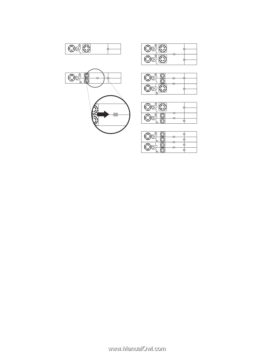
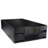
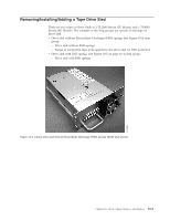
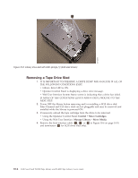
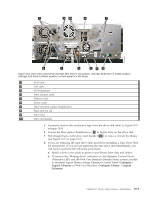
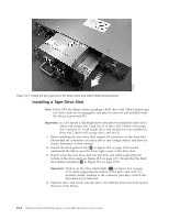
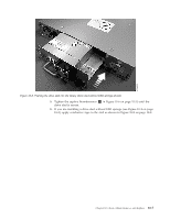
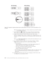
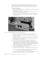
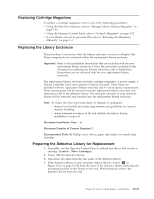
2U Library 4U Library a77ug203 Figure 10-9. Diagrams for applying conductive tape for ESD protection to the back of a drive sled installed in a 2U or 4U library Note: The small gray markers show where conductive tape should be placed to provide ESD protection. 7. Push the black tab ( 8 in Figure 10-6 on page 10-5) back underneath the library. When inserted properly, only the handle of the tab will be visible. 8. Upgrade library firmware and drive firmware to the latest version. Refer to "Configure Library: Drives" on page 5-49 to configure the drive if it is a SCSI or FC drive. Connect the drive host interface cable to the host or FC switch. Note: Go to http://support.dell.com to download the latest firmware for your library and tape drive(s). 9. Run the Library Verify test. (Operator Control Panel: Service → Library Verify). This test requires the use of a scratch (blank) cartridge. v If the test passes: - When prompted by the Operator Control Panel display and the I/O Station opens, remove the cartridge used in the test. - Close the I/O Station by pushing it back into the library. - Press Cancel to exit the Library Verify screen. - Resume normal library operations. v If the test fails, an error code will be displayed. Make note of the error, then refer to the Troubleshooting chapter in this document for additional instructions. 10. Package the failed drive sled in the same packaging in which the new sled was shipped to you and return to Dell. 10-8 Dell PowerVault TL2000 Tape Library and TL4000 Tape Library User's Guide
-
 1
1 -
2
-
3
-
4
-
5
-
6
-
7
-
8
-
9
-
10
-
11
-
12
-
13
-
14
-
15
-
16
-
17
-
18
-
19
-
20
-
21
-
22
-
23
-
24
-
25
-
26
-
27
-
28
-
29
-
30
-
31
-
32
-
33
-
34
-
35
-
36
-
37
-
38
-
39
-
40
-
41
-
42
-
43
-
44
-
45
-
46
-
47
-
48
-
49
-
50
-
51
-
52
-
53
-
54
-
55
-
56
-
57
-
58
-
59
-
60
-
61
-
62
-
63
-
64
-
65
-
66
-
67
-
68
-
69
-
70
-
71
-
72
-
73
-
74
-
75
-
76
-
77
-
78
-
79
-
80
-
81
-
82
-
83
-
84
-
85
-
86
-
87
-
88
-
89
-
90
-
91
-
92
-
93
-
94
-
95
-
96
-
97
-
98
-
99
-
100
-
101
-
102
-
103
-
104
-
105
-
106
-
107
-
108
-
109
-
110
-
111
-
112
-
113
-
114
-
115
-
116
-
117
-
118
-
119
-
120
-
121
-
122
-
123
-
124
-
125
-
126
-
127
-
128
-
129
-
130
-
131
-
132
-
133
-
134
-
135
-
136
-
137
-
138
-
139
-
140
-
141
-
142
-
143
-
144
-
145
-
146
-
147
-
148
-
149
-
150
-
151
-
152
-
153
-
154
-
155
-
156
-
157
-
158
-
159
-
160
-
161
-
162
-
163
-
164
-
165
-
166
-
167
-
168
-
169
-
170
-
171
-
172
-
173
-
174
-
175
-
176
-
177
-
178
-
179
-
180
-
181
-
182
-
183
-
184
-
185
-
186
-
187
-
188
-
189
-
190
-
191
-
192
-
193
-
194
-
195
-
196
-
197
-
198
-
199
-
200
-
201
-
202
-
 203
203 -
 204
204 -
 205
205 -
 206
206 -
 207
207 -
 208
208 -
 209
209 -
 210
210 -
 211
211 -
 212
212 -
 213
213 -
214
-
215
-
216
-
217
-
218
-
219
-
220
-
221
-
222
-
223
-
224
-
225
-
226
-
227
-
228
-
229
-
230
-
231
-
232
-
233
-
234
-
235
-
236
-
237
-
238
-
239
-
240
-
241
-
242
-
243
-
244
-
245
-
246
-
247
-
248
-
249
-
250
-
251
-
252
-
253
-
254
-
255
-
256
-
257
-
258
-
259
-
260
-
261
-
262
-
263
-
264
-
265
-
266
-
267
-
268
-
269
-
270
-
271
-
272
-
273
-
274
-
275
-
276
-
277
-
278
-
279
-
280
-
281
-
282
-
283
 |
 |