Dell PowerVault TL4000 Dell Model TL2000/TL4000 Tape Library- User's Guide - Page 218
Service, Library Verify, Run the Library Verify test Operator Control Panel
 |
View all Dell PowerVault TL4000 manuals
Add to My Manuals
Save this manual to your list of manuals |
Page 218 highlights
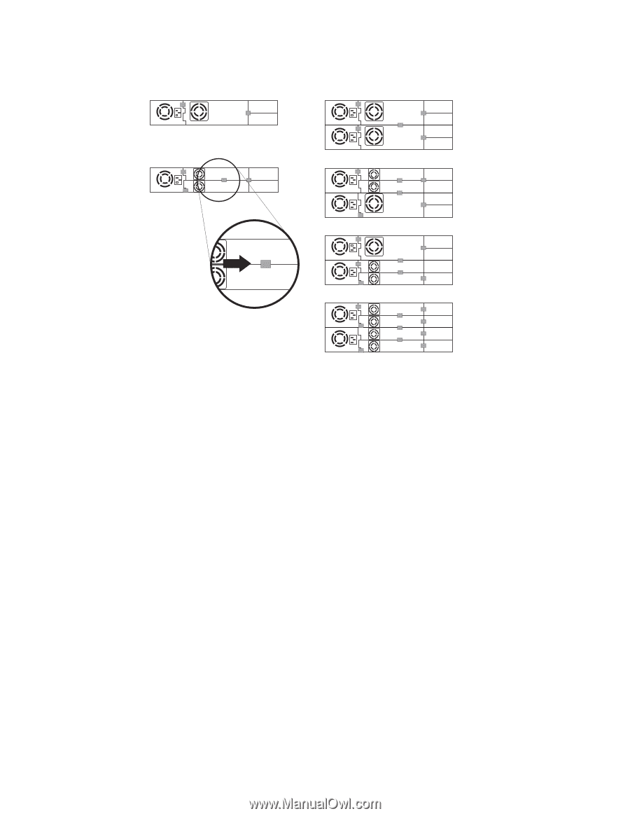
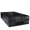
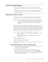
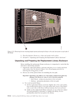
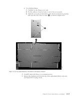
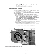
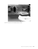
2U Library 4U Library a77ug203 Figure 10-17. Drive sled taping diagrams Note: The gray markers show where conductive tape should be placed. i. Push the black tab back underneath the drive sled. When inserted properly, only the handle of the tab will be visible. 2. Power ON the replacement library enclosure. a. If power ON is successful: 1) After power up, the Ready/Activity LED ( 1 in Figure 10-20 on page 10-22) will turn ON. a) If the following message is displayed after the library powers ON, follow the instructions in Step 1. If the message is NOT displayed skip Step 1 and proceed to Step 2. [New library detected.] [1. Perform Library Verify] [2. Power Off and insert LCC] [from old library ] [ ok ] b) The system will initialize completely. c) After confirming the pop-up, you should be able to use the interfaces. d) Run the Library Verify test (Operator Control Panel: Service → Library Verify). This diagnostic requires a blank or scratch data cartridge 2) Power OFF the replacement library enclosure. 3) You must power down, remove the CRU LCC and replace it with the original LCC to have VPD transferred from the original LCC to the new chassis. 4) Proceed to "Swapping Power Supplies" on page 10-19. b. If power ON is not successful: 10-18 Dell PowerVault TL2000 Tape Library and TL4000 Tape Library User's Guide
-
 1
1 -
2
-
3
-
4
-
5
-
6
-
7
-
8
-
9
-
10
-
11
-
12
-
13
-
14
-
15
-
16
-
17
-
18
-
19
-
20
-
21
-
22
-
23
-
24
-
25
-
26
-
27
-
28
-
29
-
30
-
31
-
32
-
33
-
34
-
35
-
36
-
37
-
38
-
39
-
40
-
41
-
42
-
43
-
44
-
45
-
46
-
47
-
48
-
49
-
50
-
51
-
52
-
53
-
54
-
55
-
56
-
57
-
58
-
59
-
60
-
61
-
62
-
63
-
64
-
65
-
66
-
67
-
68
-
69
-
70
-
71
-
72
-
73
-
74
-
75
-
76
-
77
-
78
-
79
-
80
-
81
-
82
-
83
-
84
-
85
-
86
-
87
-
88
-
89
-
90
-
91
-
92
-
93
-
94
-
95
-
96
-
97
-
98
-
99
-
100
-
101
-
102
-
103
-
104
-
105
-
106
-
107
-
108
-
109
-
110
-
111
-
112
-
113
-
114
-
115
-
116
-
117
-
118
-
119
-
120
-
121
-
122
-
123
-
124
-
125
-
126
-
127
-
128
-
129
-
130
-
131
-
132
-
133
-
134
-
135
-
136
-
137
-
138
-
139
-
140
-
141
-
142
-
143
-
144
-
145
-
146
-
147
-
148
-
149
-
150
-
151
-
152
-
153
-
154
-
155
-
156
-
157
-
158
-
159
-
160
-
161
-
162
-
163
-
164
-
165
-
166
-
167
-
168
-
169
-
170
-
171
-
172
-
173
-
174
-
175
-
176
-
177
-
178
-
179
-
180
-
181
-
182
-
183
-
184
-
185
-
186
-
187
-
188
-
189
-
190
-
191
-
192
-
193
-
194
-
195
-
196
-
197
-
198
-
199
-
200
-
201
-
202
-
203
-
204
-
205
-
206
-
207
-
208
-
209
-
210
-
211
-
212
-
 213
213 -
 214
214 -
 215
215 -
 216
216 -
 217
217 -
 218
218 -
 219
219 -
 220
220 -
 221
221 -
 222
222 -
 223
223 -
224
-
225
-
226
-
227
-
228
-
229
-
230
-
231
-
232
-
233
-
234
-
235
-
236
-
237
-
238
-
239
-
240
-
241
-
242
-
243
-
244
-
245
-
246
-
247
-
248
-
249
-
250
-
251
-
252
-
253
-
254
-
255
-
256
-
257
-
258
-
259
-
260
-
261
-
262
-
263
-
264
-
265
-
266
-
267
-
268
-
269
-
270
-
271
-
272
-
273
-
274
-
275
-
276
-
277
-
278
-
279
-
280
-
281
-
282
-
283
 |
 |