Dell PowerVault TL4000 Dell Model TL2000/TL4000 Tape Library- User's Guide - Page 277
Index, A, B, C, D, E, F, G, H, I, I/O Station, configuring
 |
View all Dell PowerVault TL4000 manuals
Add to My Manuals
Save this manual to your list of manuals |
Page 277 highlights
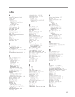
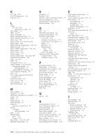
Index A Access PIN, Operator Control Panel 5-26 accessibility keyboard H-1 repeat rate of up and down buttons H-1 shortcut keys H-1 accessor 1-5 accessory package 4-2 active slots 5-20, 5-44 Active Slots 4-19 air quality 4-1 air vents, front panel 1-1 AME 5-47 Application Managed Encryption (AME) 4-22 ASC C-1 ASCQ C-1 auto clean 5-20, 5-44 Auto Clean 4-19 B Bar Code Labels 6-4 guidelines for using 6-5 bar code reader 1-5 bootcode firmware, current level 5-34 BOP 5-38 Border Gateway Protocol (BGP) 1-7 C cable, host interface 4-11 Cartridge 1-10, 6-1 capacity scaling 6-1 cleaning 6-4 compatibility 6-2 data 6-1 proper handling 6-7 specifications 6-9 Write-Protect Switch 6-6 cartridge magazines 1-1, 4-32 Cartridge, environment 6-8 cartridge, suspect 2-2 cartridges inserting in library 4-36 populating library 4-36 Cartridges, insert and remove 5-64 channel calibration 1-10 choosing a location 4-1 clean drive 5-57 cleaning slot 5-65 clearance 4-1 Configure menu network settings 4-15 configuring library using Web User Interface 4-15 configuring the library 4-14 control keys 5-7 control path drive 5-35, 5-49 control path failover 3-2, 5-46 control paths 5-23 multiple 3-2 using multiple for control path failover 3-2 D daisy-chaining 3-9 Data Cartridge 5-64 data transfer rate 1-8 DCS 5-65 dedicated cleaning slot A-2 default settings 5-27 description 1-1 desktop installation 4-1 Device drivers supported 1-13 DHCP 4-15, 4-24, 5-24, 5-50 Diagnostics 5-60 display contrast 5-32 dll 7-12 Drive channel calibration 1-10 power management 1-10 speed matching 1-10 drive configuration 5-49 Drive Density 5-38 Drive Diagnostics 5-31, 5-60 drive dump, saving to host 5-60 drive firmware, current version 5-35 drive interface 5-23 Drive Log 5-59 drive serial number 5-35 drive sled description 1-8 drive status 5-38 drive, clean 5-57 E EC 5-14 ED 5-14 EKM 4-22 EKM Server Setting 4-22 element addresses 3-3, A-2, A-3 element addressing A-1 element types A-1 Encryption 1-5, 4-22 environment 1-13 operating 1-13 particulates 1-13 environmental specifications 1-11 Error Codes 8-1 Error LEDs 7-7 Error log 8-1 Ethernet Port 1-3 Export Media 4-36, 5-16, 5-42, 5-64 F factory default settings 5-27 fan vents 1-3 feature activation key 5-46 features optional drives 1-8 Fibre Channel 3-7 Fibre Channel interface cables and speeds 3-10 sharing on a SAN 3-10 zoning 3-10 Fibre Channel ports 3-9 Firmware updating using ITDT Tool 9-4 firmware, upgrade 5-62 foot pads, installing 4-3 front panel components 1-1 G Gateway address 4-15 Gateway Address 4-24, 5-24, 5-50 glossary I-1 H Host Attachment 7-12 host bus adapter 3-6 host connection, verifying 4-32 host interface cable 4-11 host interface connectors 1-3 host interfaces 3-7 host preparation 4-31 humidity 4-1 I I/O Station 1-1, 4-32, 5-64 I/O Station, configuring 5-65 I/O Station, open and close 5-65 identifying a suspect cartridge 1-1, 2-2 Import Media 4-36, 5-16, 5-42, 5-64 installation 4-1 Interface 7-12 interfaces 3-7 interfaces, supported 1-8 Internet Protocol version 4 1-7 Internet Protocol version 6 1-7 Inventory 5-14, 5-43 IP address 4-15, 5-34 IP Address 4-24, 5-24, 5-50 IP Stack 5-24 IPv4 1-7 IPv6 1-7 ITDT Tool 9-4 X-1
-
 1
1 -
2
-
3
-
4
-
5
-
6
-
7
-
8
-
9
-
10
-
11
-
12
-
13
-
14
-
15
-
16
-
17
-
18
-
19
-
20
-
21
-
22
-
23
-
24
-
25
-
26
-
27
-
28
-
29
-
30
-
31
-
32
-
33
-
34
-
35
-
36
-
37
-
38
-
39
-
40
-
41
-
42
-
43
-
44
-
45
-
46
-
47
-
48
-
49
-
50
-
51
-
52
-
53
-
54
-
55
-
56
-
57
-
58
-
59
-
60
-
61
-
62
-
63
-
64
-
65
-
66
-
67
-
68
-
69
-
70
-
71
-
72
-
73
-
74
-
75
-
76
-
77
-
78
-
79
-
80
-
81
-
82
-
83
-
84
-
85
-
86
-
87
-
88
-
89
-
90
-
91
-
92
-
93
-
94
-
95
-
96
-
97
-
98
-
99
-
100
-
101
-
102
-
103
-
104
-
105
-
106
-
107
-
108
-
109
-
110
-
111
-
112
-
113
-
114
-
115
-
116
-
117
-
118
-
119
-
120
-
121
-
122
-
123
-
124
-
125
-
126
-
127
-
128
-
129
-
130
-
131
-
132
-
133
-
134
-
135
-
136
-
137
-
138
-
139
-
140
-
141
-
142
-
143
-
144
-
145
-
146
-
147
-
148
-
149
-
150
-
151
-
152
-
153
-
154
-
155
-
156
-
157
-
158
-
159
-
160
-
161
-
162
-
163
-
164
-
165
-
166
-
167
-
168
-
169
-
170
-
171
-
172
-
173
-
174
-
175
-
176
-
177
-
178
-
179
-
180
-
181
-
182
-
183
-
184
-
185
-
186
-
187
-
188
-
189
-
190
-
191
-
192
-
193
-
194
-
195
-
196
-
197
-
198
-
199
-
200
-
201
-
202
-
203
-
204
-
205
-
206
-
207
-
208
-
209
-
210
-
211
-
212
-
213
-
214
-
215
-
216
-
217
-
218
-
219
-
220
-
221
-
222
-
223
-
224
-
225
-
226
-
227
-
228
-
229
-
230
-
231
-
232
-
233
-
234
-
235
-
236
-
237
-
238
-
239
-
240
-
241
-
242
-
243
-
244
-
245
-
246
-
247
-
248
-
249
-
250
-
251
-
252
-
253
-
254
-
255
-
256
-
257
-
258
-
259
-
260
-
261
-
262
-
263
-
264
-
265
-
266
-
267
-
268
-
269
-
270
-
271
-
 272
272 -
 273
273 -
 274
274 -
 275
275 -
 276
276 -
 277
277 -
 278
278 -
 279
279 -
 280
280 -
 281
281 -
 282
282 -
283
 |
 |