HP NetServer AA 4000 HP Netserver AA Solution Administrator's Guide v - Page 44
Interconnect States, Table 2-6
 |
View all HP NetServer AA 4000 manuals
Add to My Manuals
Save this manual to your list of manuals |
Page 44 highlights
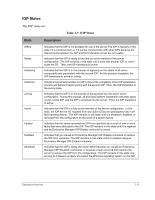
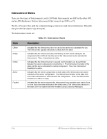
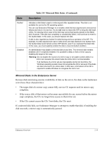
Interconnect States There are two types of Interconnects: an IL (IOP link) that connects one IOP to the other IOP, and an ESI (Endurance System Interconnect) that connects an IOP to a CE. The IL cables provide a path for communicating system states and status information. This path also provides the mirror copy data path. The Interconnect states are: Table 2-6 Interconnect States State Description Offline Ready Online Active Faulted Indicates that the Interconnect is not in use by the server but is available for use. The Interconnect typically transitions to ready from this state. Indicates that the Interconnect was activated by an IOP and is waiting for the component (CE or IOP) at the other end of the interconnect to also activate the Interconnect. Then, it transitions to online. Indicates that the Interconnect is in use and communication can be performed between the server components connected by it. The Interconnect remains in this state until the server activates the remote component. Then, the Interconnect transitions to active. Indicates that the server components on both sides of the Interconnect are active members of the server configuration. The Interconnect remains in this state until one of the components is removed from the configuration. Then, the Interconnect transitions to offline or ready. Indicates that the server removed the Interconnect from operation as a result of one or more faults that were attributed to the Interconnect. The Interconnect remains in this state until it is repaired and then enabled (using Endurance Manager). 2-16 HP Netserver AA Solution Administrator's Guide
-
 1
1 -
2
-
3
-
4
-
5
-
6
-
7
-
8
-
9
-
10
-
11
-
12
-
13
-
14
-
15
-
16
-
17
-
18
-
19
-
20
-
21
-
22
-
23
-
24
-
25
-
26
-
27
-
28
-
29
-
30
-
31
-
32
-
33
-
34
-
35
-
36
-
37
-
38
-
 39
39 -
 40
40 -
 41
41 -
 42
42 -
 43
43 -
 44
44 -
 45
45 -
 46
46 -
 47
47 -
 48
48 -
 49
49 -
50
-
51
-
52
-
53
-
54
-
55
-
56
-
57
-
58
-
59
-
60
-
61
-
62
-
63
-
64
-
65
-
66
-
67
-
68
-
69
-
70
-
71
-
72
-
73
-
74
-
75
-
76
-
77
-
78
-
79
-
80
-
81
-
82
-
83
-
84
-
85
-
86
-
87
-
88
-
89
-
90
-
91
-
92
-
93
-
94
-
95
-
96
-
97
-
98
-
99
-
100
-
101
-
102
-
103
-
104
-
105
-
106
-
107
-
108
-
109
-
110
-
111
-
112
-
113
-
114
-
115
-
116
-
117
-
118
-
119
-
120
-
121
-
122
-
123
-
124
-
125
-
126
-
127
-
128
-
129
-
130
-
131
-
132
-
133
-
134
-
135
-
136
-
137
-
138
-
139
-
140
-
141
-
142
-
143
-
144
-
145
-
146
-
147
-
148
-
149
-
150
-
151
-
152
-
153
-
154
-
155
-
156
-
157
-
158
-
159
-
160
-
161
-
162
-
163
-
164
-
165
-
166
-
167
-
168
-
169
-
170
-
171
-
172
-
173
-
174
-
175
-
176
-
177
-
178
-
179
-
180
-
181
-
182
-
183
-
184
-
185
-
186
-
187
-
188
-
189
-
190
-
191
-
192
-
193
-
194
-
195
-
196
-
197
-
198
-
199
-
200
-
201
-
202
-
203
-
204
-
205
-
206
-
207
-
208
-
209
-
210
-
211
-
212
-
213
-
214
-
215
-
216
-
217
-
218
-
219
-
220
-
221
-
222
-
223
-
224
-
225
-
226
-
227
-
228
-
229
-
230
-
231
-
232
-
233
-
234
-
235
-
236
-
237
-
238
-
239
-
240
-
241
-
242
-
243
-
244
-
245
-
246
-
247
-
248
-
249
-
250
-
251
-
252
-
253
-
254
-
255
-
256
-
257
-
258
-
259
-
260
-
261
-
262
-
263
-
264
-
265
-
266
-
267
-
268
-
269
-
270
-
271
-
272
 |
 |