HP NetServer AA 4000 HP Netserver AA Solution Administrator's Guide v - Page 45
MIC Port State Display Lights, after, Table 2-7
 |
View all HP NetServer AA 4000 manuals
Add to My Manuals
Save this manual to your list of manuals |
Page 45 highlights
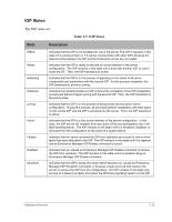
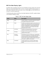
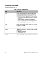
MIC Port State Display Lights Each IOP collects and displays the status of its local MIC ports along with the status of the CE MIC ports connected through the fiber. CE status is relayed to the IOP with the assistance of MIC firmware; therefore, the CE port status is only available after the CE MIC BIOS has set its ports to a software-enabled state. The following table explains the MIC port state lights displayed on the MIC's graphical display in the Endurance Manager window. Table 2-7 MIC Port State Display Lights Color Green Red Orange Gray Black State Good Failed Lost Power PCI Reset Unknown/ Unavailable Uninitialized Description The MIC hardware is successfully sending and receiving fiber signals through the fiber connector. The MIC port has detected a break in communication over the path, which may be caused by a fiber disconnection or a failure in the transmitters or receivers associated with this path. This light does not indicate which end of the path may have failed and does not imply that the MIC reporting this state is broken. The MIC port at the opposite end of the cable has detected a local DC-low condition (power loss). The MIC port at the opposite end of the cable has detected a PCI bus reset. This state occurs only on CE MIC ports. It indicates that, from the IOP's perspective, no information about the state of this port has been received. Normally the CE MIC firmware relays the local port status to the IOP MICs. This does not occur, however, until the CE MICs are powered on and able to establish communication. The MIC hardware has not sensed any fiber signals through the fiber connector since the IOP or CE has booted. Endurance Overview 2-17
-
 1
1 -
2
-
3
-
4
-
5
-
6
-
7
-
8
-
9
-
10
-
11
-
12
-
13
-
14
-
15
-
16
-
17
-
18
-
19
-
20
-
21
-
22
-
23
-
24
-
25
-
26
-
27
-
28
-
29
-
30
-
31
-
32
-
33
-
34
-
35
-
36
-
37
-
38
-
39
-
 40
40 -
 41
41 -
 42
42 -
 43
43 -
 44
44 -
 45
45 -
 46
46 -
 47
47 -
 48
48 -
 49
49 -
 50
50 -
51
-
52
-
53
-
54
-
55
-
56
-
57
-
58
-
59
-
60
-
61
-
62
-
63
-
64
-
65
-
66
-
67
-
68
-
69
-
70
-
71
-
72
-
73
-
74
-
75
-
76
-
77
-
78
-
79
-
80
-
81
-
82
-
83
-
84
-
85
-
86
-
87
-
88
-
89
-
90
-
91
-
92
-
93
-
94
-
95
-
96
-
97
-
98
-
99
-
100
-
101
-
102
-
103
-
104
-
105
-
106
-
107
-
108
-
109
-
110
-
111
-
112
-
113
-
114
-
115
-
116
-
117
-
118
-
119
-
120
-
121
-
122
-
123
-
124
-
125
-
126
-
127
-
128
-
129
-
130
-
131
-
132
-
133
-
134
-
135
-
136
-
137
-
138
-
139
-
140
-
141
-
142
-
143
-
144
-
145
-
146
-
147
-
148
-
149
-
150
-
151
-
152
-
153
-
154
-
155
-
156
-
157
-
158
-
159
-
160
-
161
-
162
-
163
-
164
-
165
-
166
-
167
-
168
-
169
-
170
-
171
-
172
-
173
-
174
-
175
-
176
-
177
-
178
-
179
-
180
-
181
-
182
-
183
-
184
-
185
-
186
-
187
-
188
-
189
-
190
-
191
-
192
-
193
-
194
-
195
-
196
-
197
-
198
-
199
-
200
-
201
-
202
-
203
-
204
-
205
-
206
-
207
-
208
-
209
-
210
-
211
-
212
-
213
-
214
-
215
-
216
-
217
-
218
-
219
-
220
-
221
-
222
-
223
-
224
-
225
-
226
-
227
-
228
-
229
-
230
-
231
-
232
-
233
-
234
-
235
-
236
-
237
-
238
-
239
-
240
-
241
-
242
-
243
-
244
-
245
-
246
-
247
-
248
-
249
-
250
-
251
-
252
-
253
-
254
-
255
-
256
-
257
-
258
-
259
-
260
-
261
-
262
-
263
-
264
-
265
-
266
-
267
-
268
-
269
-
270
-
271
-
272
 |
 |