HP Sprout Pro G2 Maintenance & Service Guide - Page 48
Converter board
 |
View all HP Sprout Pro G2 manuals
Add to My Manuals
Save this manual to your list of manuals |
Page 48 highlights
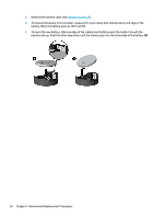
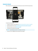
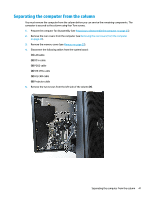
Converter board When viewing the back of the computer, the converter board is located to the left of the system board. To remove the converter board: 1. Prepare the computer for disassembly (see Preparing to disassemble the computer on page 23). 2. Remove the right rear cover (see Removing the rear covers from the computer on page 24). 3. Remove the memory cover (see Memory on page 29). 4. Disconnect the two cables from the board (1). NOTE: Use the backlight cable specific to the display manufacturer. 5. Remove the Torx screw (2) that secures the board to the computer. 38 Chapter 4 Removal and Replacement Procedures
-
 1
1 -
2
-
3
-
4
-
5
-
6
-
7
-
8
-
9
-
10
-
11
-
12
-
13
-
14
-
15
-
16
-
17
-
18
-
19
-
20
-
21
-
22
-
23
-
24
-
25
-
26
-
27
-
28
-
29
-
30
-
31
-
32
-
33
-
34
-
35
-
36
-
37
-
38
-
39
-
40
-
41
-
42
-
 43
43 -
 44
44 -
 45
45 -
 46
46 -
 47
47 -
 48
48 -
 49
49 -
 50
50 -
 51
51 -
 52
52 -
 53
53 -
54
-
55
-
56
-
57
-
58
-
59
-
60
-
61
-
62
-
63
-
64
-
65
-
66
-
67
-
68
-
69
-
70
-
71
-
72
-
73
-
74
-
75
-
76
-
77
-
78
-
79
-
80
-
81
-
82
-
83
-
84
-
85
-
86
-
87
-
88
-
89
-
90
-
91
-
92
-
93
-
94
-
95
-
96
-
97
-
98
-
99
-
100
-
101
-
102
-
103
-
104
-
105
-
106
-
107
-
108
-
109
-
110
-
111
-
112
-
113
-
114
-
115
-
116
-
117
-
118
-
119
-
120
-
121
-
122
-
123
-
124
-
125
-
126
-
127
-
128
-
129
-
130
-
131
-
132
-
133
-
134
-
135
-
136
 |
 |
Converter board
When viewing the back of the computer, the converter board is located to the left of the system board.
To remove the converter board:
1.
Prepare the computer for disassembly (see
Preparing to disassemble the computer
on page
23
).
2.
Remove the right rear cover (see
Removing the rear covers from the computer
on page
24
).
3.
Remove the memory cover (see
Memory
on page
29
).
4.
Disconnect the two cables from the board
(1)
.
NOTE:
Use the backlight cable
specific
to the display manufacturer.
5.
Remove the Torx screw
(2)
that secures the board to the computer.
38
Chapter 4
Removal and Replacement Procedures