HP Sprout Pro G2 Maintenance & Service Guide - Page 51
Separating the computer from the column, DC In cable
 |
View all HP Sprout Pro G2 manuals
Add to My Manuals
Save this manual to your list of manuals |
Page 51 highlights
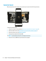
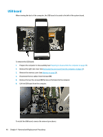
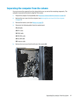
Separating the computer from the column You must remove the computer from the column before you can service the remaining components. The computer is secured to the column using four Torx screws. 1. Prepare the computer for disassembly (see Preparing to disassemble the computer on page 23). 2. Remove the rear covers from the computer (see Removing the rear covers from the computer on page 24). 3. Remove the memory cover (see Memory on page 29). 4. Disconnect the following cables from the system board: (1) LAN cable (2) DC In cable (3) POGO cable (4) SYS CTRL cable (5) H/L CAM cable (6) Projector cable 5. Remove the two screws from the left side of the column (7). Separating the computer from the column 41
-
 1
1 -
2
-
3
-
4
-
5
-
6
-
7
-
8
-
9
-
10
-
11
-
12
-
13
-
14
-
15
-
16
-
17
-
18
-
19
-
20
-
21
-
22
-
23
-
24
-
25
-
26
-
27
-
28
-
29
-
30
-
31
-
32
-
33
-
34
-
35
-
36
-
37
-
38
-
39
-
40
-
41
-
42
-
43
-
44
-
45
-
 46
46 -
 47
47 -
 48
48 -
 49
49 -
 50
50 -
 51
51 -
 52
52 -
 53
53 -
 54
54 -
 55
55 -
 56
56 -
57
-
58
-
59
-
60
-
61
-
62
-
63
-
64
-
65
-
66
-
67
-
68
-
69
-
70
-
71
-
72
-
73
-
74
-
75
-
76
-
77
-
78
-
79
-
80
-
81
-
82
-
83
-
84
-
85
-
86
-
87
-
88
-
89
-
90
-
91
-
92
-
93
-
94
-
95
-
96
-
97
-
98
-
99
-
100
-
101
-
102
-
103
-
104
-
105
-
106
-
107
-
108
-
109
-
110
-
111
-
112
-
113
-
114
-
115
-
116
-
117
-
118
-
119
-
120
-
121
-
122
-
123
-
124
-
125
-
126
-
127
-
128
-
129
-
130
-
131
-
132
-
133
-
134
-
135
-
136
 |
 |
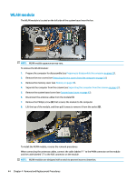
Separating the computer from the column
You must remove the computer from the column before you can service the remaining components. The
computer is secured to the column using four Torx screws.
1.
Prepare the computer for disassembly (see
Preparing to disassemble the computer
on page
23
).
2.
Remove the rear covers from the computer (see
Removing the rear covers from the computer
on page
24
).
3.
Remove the memory cover (see
Memory
on page
29
).
4.
Disconnect the following cables from the system board:
(1)
LAN cable
(2)
DC In cable
(3)
POGO cable
(4)
SYS CTRL cable
(5)
H/L CAM cable
(6)
Projector cable
5.
Remove the two screws from the left side of the column
(7)
.
Separating the computer from the column
41