HP Sprout Pro G2 Maintenance & Service Guide - Page 69
Webcam module
 |
View all HP Sprout Pro G2 manuals
Add to My Manuals
Save this manual to your list of manuals |
Page 69 highlights
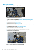
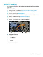
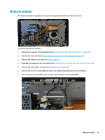
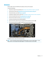
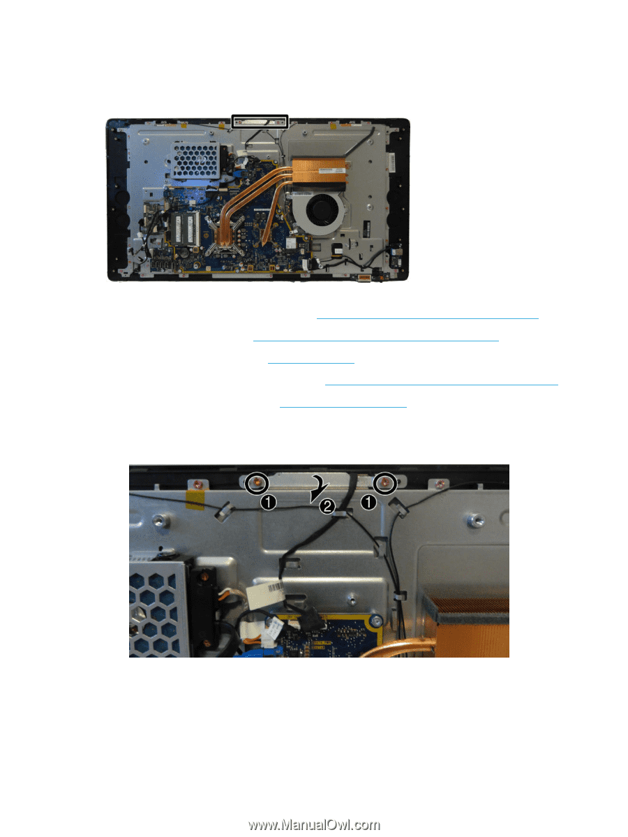
Webcam module The webcam module is located at the top of the computer beneath the outer plastic trim. To remove the webcam module: 1. Prepare the computer for disassembly (see Preparing to disassemble the computer on page 23). 2. Remove the rear covers (see Removing the rear covers from the computer on page 24). 3. Remove the memory cover (see Memory on page 29). 4. Separate the computer from the column (see Separating the computer from the column on page 41). 5. Remove the outer plastic trim (see Outer plastic trim on page 55). 6. Remove the two Torx screws (1) that secure the webcam module bracket to the computer. 7. Lift and rotate the assembly to gain access to the connector on the module (2). Webcam module 59
-
 1
1 -
2
-
3
-
4
-
5
-
6
-
7
-
8
-
9
-
10
-
11
-
12
-
13
-
14
-
15
-
16
-
17
-
18
-
19
-
20
-
21
-
22
-
23
-
24
-
25
-
26
-
27
-
28
-
29
-
30
-
31
-
32
-
33
-
34
-
35
-
36
-
37
-
38
-
39
-
40
-
41
-
42
-
43
-
44
-
45
-
46
-
47
-
48
-
49
-
50
-
51
-
52
-
53
-
54
-
55
-
56
-
57
-
58
-
59
-
60
-
61
-
62
-
63
-
 64
64 -
 65
65 -
 66
66 -
 67
67 -
 68
68 -
 69
69 -
 70
70 -
 71
71 -
 72
72 -
 73
73 -
 74
74 -
75
-
76
-
77
-
78
-
79
-
80
-
81
-
82
-
83
-
84
-
85
-
86
-
87
-
88
-
89
-
90
-
91
-
92
-
93
-
94
-
95
-
96
-
97
-
98
-
99
-
100
-
101
-
102
-
103
-
104
-
105
-
106
-
107
-
108
-
109
-
110
-
111
-
112
-
113
-
114
-
115
-
116
-
117
-
118
-
119
-
120
-
121
-
122
-
123
-
124
-
125
-
126
-
127
-
128
-
129
-
130
-
131
-
132
-
133
-
134
-
135
-
136
 |
 |
Webcam module
The webcam module is located at the top of the computer beneath the outer plastic trim.
To remove the webcam module:
1.
Prepare the computer for disassembly (see
Preparing to disassemble the computer
on page
23
).
2.
Remove the rear covers (see
Removing the rear covers from the computer
on page
24
).
3.
Remove the memory cover (see
Memory
on page
29
).
4.
Separate the computer from the column (see
Separating the computer from the column
on page
41
).
5.
Remove the outer plastic trim (see
Outer plastic trim
on page
55
).
6.
Remove the two Torx screws
(1)
that secure the webcam module bracket to the computer.
7.
Lift and rotate the assembly to gain access to the connector on the module
(2)
.
Webcam module
59