HP Sprout Pro G2 Maintenance & Service Guide - Page 55
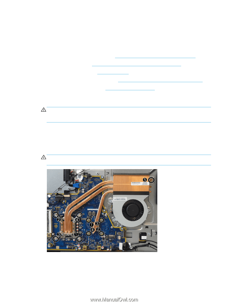
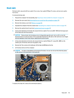
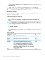
Heat sink, smaller part of the heat sink over the graphics chip.
 |
View all HP Sprout Pro G2 manuals
Add to My Manuals
Save this manual to your list of manuals |
Page 55 highlights
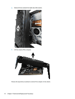
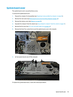
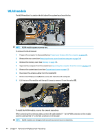
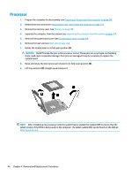
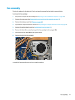
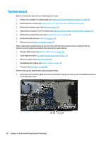
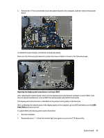
Heat sink The heat sink is secured with four captive Torx screws, four captive Phillips #1 screws, and one non-captive Torx screw. To remove the heat sink: 1. Prepare the computer for disassembly (see Preparing to disassemble the computer on page 23). 2. Remove the rear covers (see Removing the rear covers from the computer on page 24). 3. Remove the memory cover (see Memory on page 29). 4. Separate the computer from the column (see Separating the computer from the column on page 41). 5. Remove the system board cover (see System board cover on page 43). 6. In the order indicated on the heat sink, loosen the four captive Torx screws (1) - (4) from the larger part of the heat sink over the processor. CAUTION: Remove heat sink retaining screws in diagonally opposite pairs (as in an X) to even the downward forces on the processor. This is especially important as the pins on the socket are very fragile and any damage to them may require replacing the system board. 7. In the order indicated on the heat sink, loosen the four captive Phillips #1 screws (1) - (4) from the smaller part of the heat sink over the graphics chip. 8. Remove the Torx screw on the right part of the heat sink (5) above the fan. 9. Lift the heat sink out of the computer. CAUTION: To reduce a degradation in thermal performance, be sure not to touch the thermal grease on the surface of the processor or the heat sink. To replace the heat sink, reverse the removal procedures. Heat sink 45
-
 1
1 -
2
-
3
-
4
-
5
-
6
-
7
-
8
-
9
-
10
-
11
-
12
-
13
-
14
-
15
-
16
-
17
-
18
-
19
-
20
-
21
-
22
-
23
-
24
-
25
-
26
-
27
-
28
-
29
-
30
-
31
-
32
-
33
-
34
-
35
-
36
-
37
-
38
-
39
-
40
-
41
-
42
-
43
-
44
-
45
-
46
-
47
-
48
-
49
-
 50
50 -
 51
51 -
 52
52 -
 53
53 -
 54
54 -
 55
55 -
 56
56 -
 57
57 -
 58
58 -
 59
59 -
 60
60 -
61
-
62
-
63
-
64
-
65
-
66
-
67
-
68
-
69
-
70
-
71
-
72
-
73
-
74
-
75
-
76
-
77
-
78
-
79
-
80
-
81
-
82
-
83
-
84
-
85
-
86
-
87
-
88
-
89
-
90
-
91
-
92
-
93
-
94
-
95
-
96
-
97
-
98
-
99
-
100
-
101
-
102
-
103
-
104
-
105
-
106
-
107
-
108
-
109
-
110
-
111
-
112
-
113
-
114
-
115
-
116
-
117
-
118
-
119
-
120
-
121
-
122
-
123
-
124
-
125
-
126
-
127
-
128
-
129
-
130
-
131
-
132
-
133
-
134
-
135
-
136
 |
 |